Protection cap for optical fiber adapter

a protection cap and optical fiber technology, applied in the direction of connection end caps, coupling device connections, instruments, etc., can solve the problems of operator's eyes being easily injured, fiber ends may be damaged by adverse environmental hazards, and affect the optical transmission capacity of fibers

Active Publication Date: 2014-04-08
EZONTEK TECH
View PDF33 Cites 17 Cited by
  • Summary
  • Abstract
  • Description
  • Claims
  • Application Information

AI Technical Summary

Problems solved by technology

Often, fiber ends may be damaged by adverse environmental hazards, particularly at the location where optical fibers terminate in connectors.
In particular, dust, dirt, and debris may impair the optical transmission capabilities of the fiber.
Also, since a laser beam passes through the fiber, an operator's eyes may easily be injured while the connector is not in use or is not covered.

Method used


Image

  • Protection cap for optical fiber adapter
  • Protection cap for optical fiber adapter
  • Protection cap for optical fiber adapter

Examples


Embodiment Construction

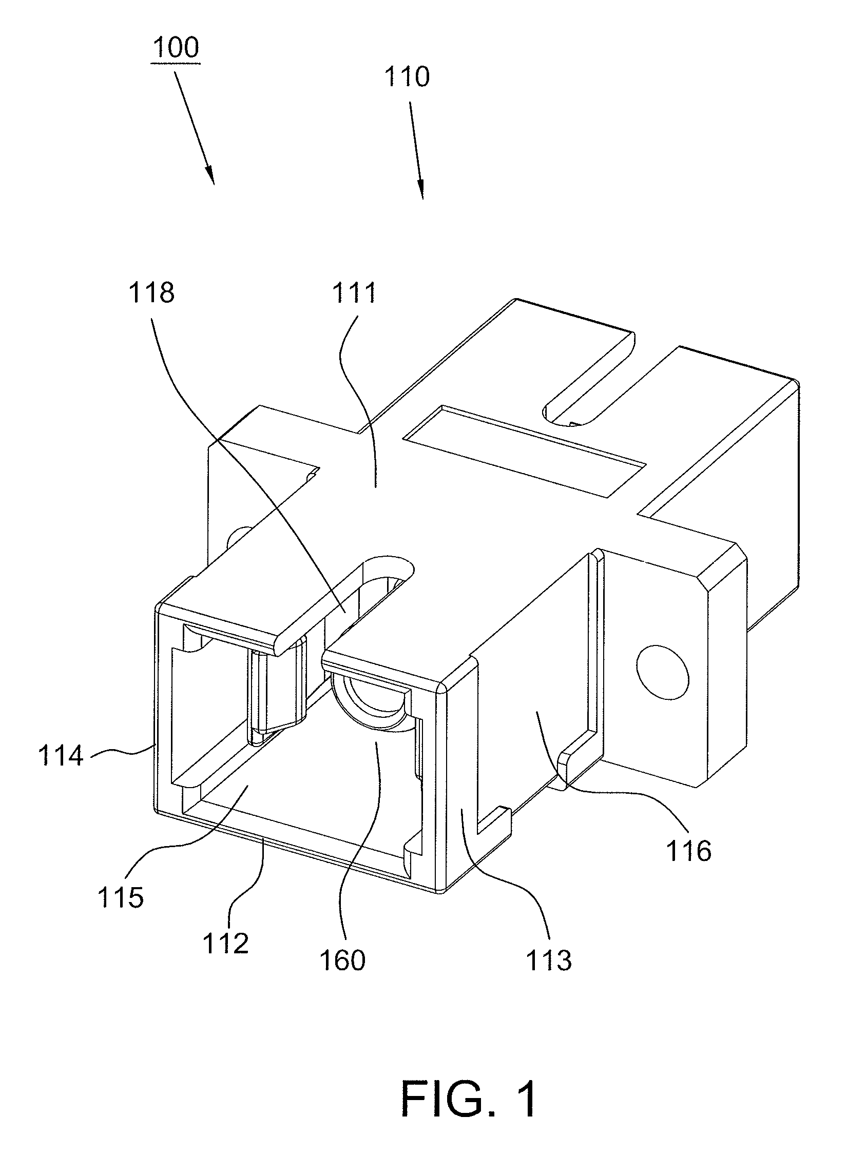
[0015]Referring to FIG. 1, a conventional optical fiber adapter 100 includes a molded main body 110. The main body 110 is of rectangular shape and has an axial accommodation room 115 defined by a top side-wall 111, a bottom side-wall 112, a right side-wall 113 and a left side-wall 114. An inner housing 160 is placed within the accommodation room 115. A guiding slot 118 is defined in the top side-wall 111. A recess 116 is formed on each of the right side-wall 113 and the left side-wall 114.

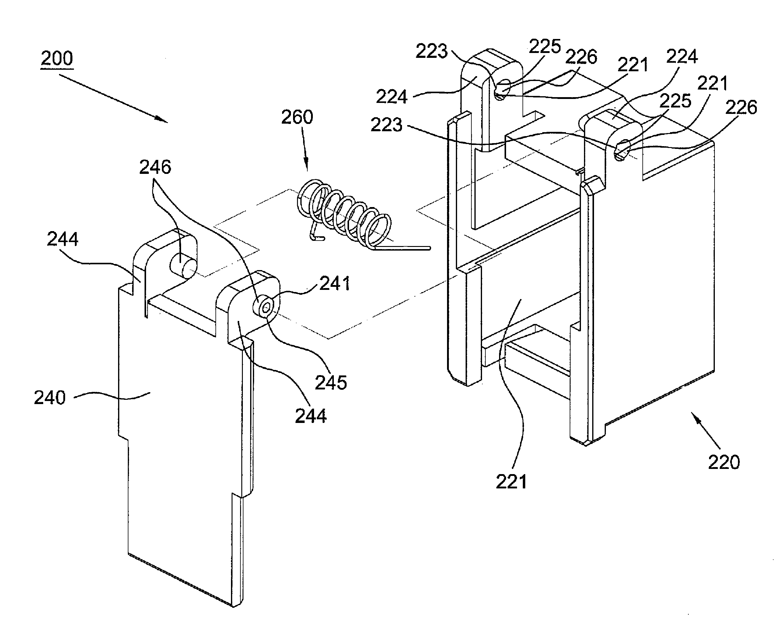
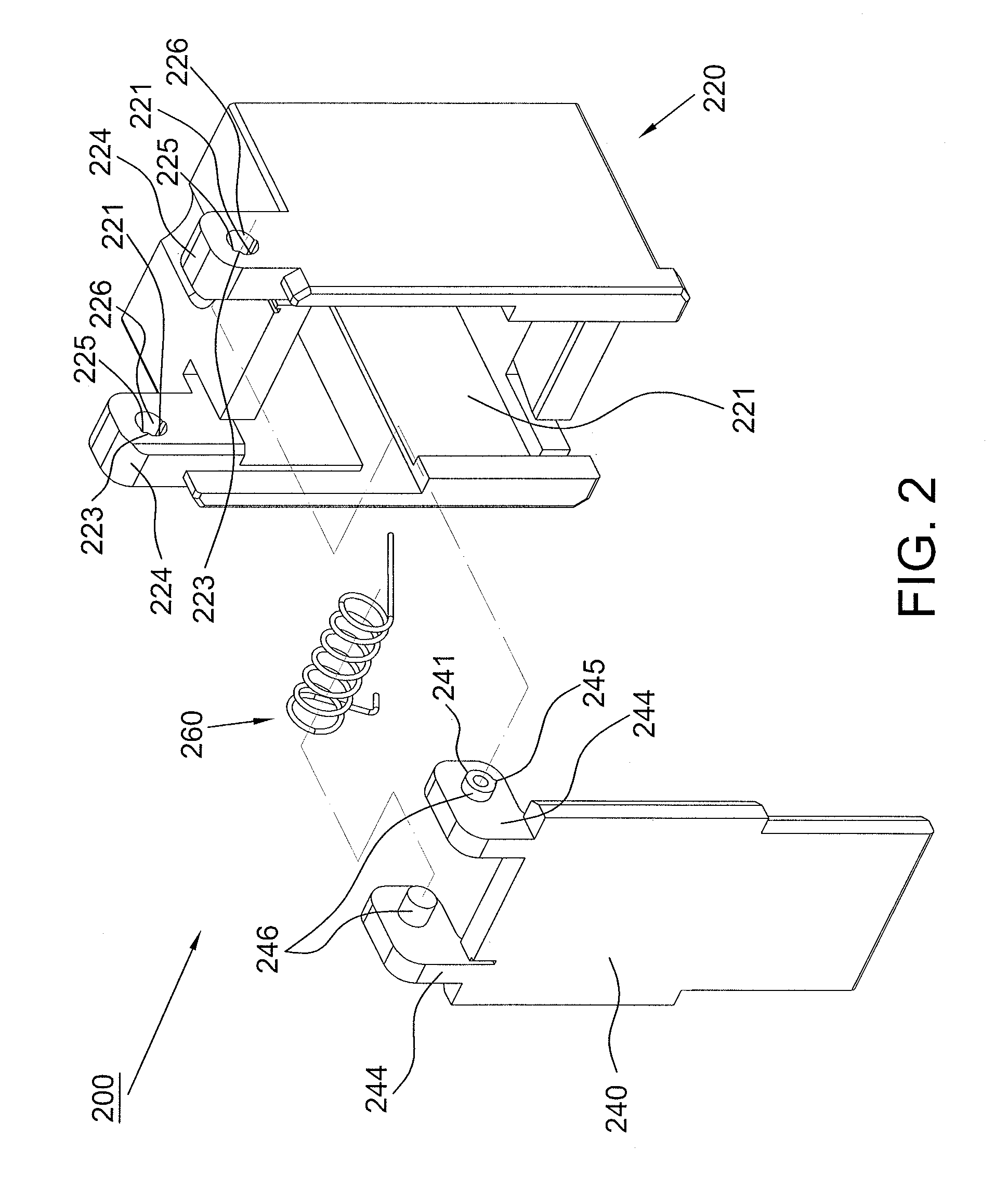
[0016]Referring to FIGS. 2 and 3, the protection cap 200 for an optical fiber adapter according to the present disclosure includes a casing 220, a covering lid 240 pivotally connected to the casing 220, and a coil spring 260 exerting a force on the covering lid 240. The casing 220 defines a passage 221 for receiving the main body 110 of the optical fiber adapter 100 A pair of supporting lugs 224 is formed on the casing 220 and each of the supporting lugs 224 defines a shaft hole 226. The covering l...


PUM


Abstract

A protect cap for an optical fiber adapter according to the present disclosure is provided. The protect cap includes a casing defining a passage for receiving the optical fiber adapter, a pair of supporting lugs formed on the casing, a covering lid, and a pair of supporting arms extending from the covering lid. Each of the supporting lugs defines a shaft hole. Each of the supporting arms is provided with a shaft, wherein the shafts are positioned in the shaft holes, respectively such that the covering lid is pivotally connected to the casing. A first protrusion is formed on one of the shafts and a second protrusion is formed on an inner surface of one of the shaft holes. When the shafts are rotated to bring the first protrusion into contact with the second protrusion, the covering lid is kept in an open position with respect to the casing.

Description

CROSS REFERENCE TO RELATED APPLICATION[0001]This application claims the priority benefit of China Patent Application Serial Number 201110332114.2 filed Oct. 27, 2011, the full disclosure of which is incorporated herein by reference.BACKGROUND OF THE INVENTION[0002]1. Field of the Invention[0003]The present invention relates to a protection cap, and more particularly, to a protection cap for an optical fiber adapter.[0004]2. Description of the Related Art[0005]Recently, the optical fiber has been widely used as signal transmission media because of its high bandwidth and low loss nature. Often, fiber ends may be damaged by adverse environmental hazards, particularly at the location where optical fibers terminate in connectors. In particular, dust, dirt, and debris may impair the optical transmission capabilities of the fiber. Also, since a laser beam passes through the fiber, an operator's eyes may easily be injured while the connector is not in use or is not covered. Hence, the matin...

Claims


Application Information

Patent Timeline
Patent Type & Authority Patents(United States)
IPC IPC(8): H01R39/27H01R4/22H01R13/44G02B23/16
CPCG02B6/3849
Inventor LIN, SUNG ANLIN, SUNG CHI
Owner EZONTEK TECH
Why Eureka
Try Eureka