
Electronic device shield and connector case

a shield and connector technology, applied in the direction of coupling device connections, electric discharge lamps, instruments, etc., can solve problems such as failure of internal conductors, and achieve the effect of avoiding obscuring the purpos

Inactive Publication Date: 2014-04-08
ZEOLLA GIORGIO
View PDF23 Cites 30 Cited by
  • Summary
  • Abstract
  • Description
  • Claims
  • Application Information

AI Technical Summary

Benefits of technology

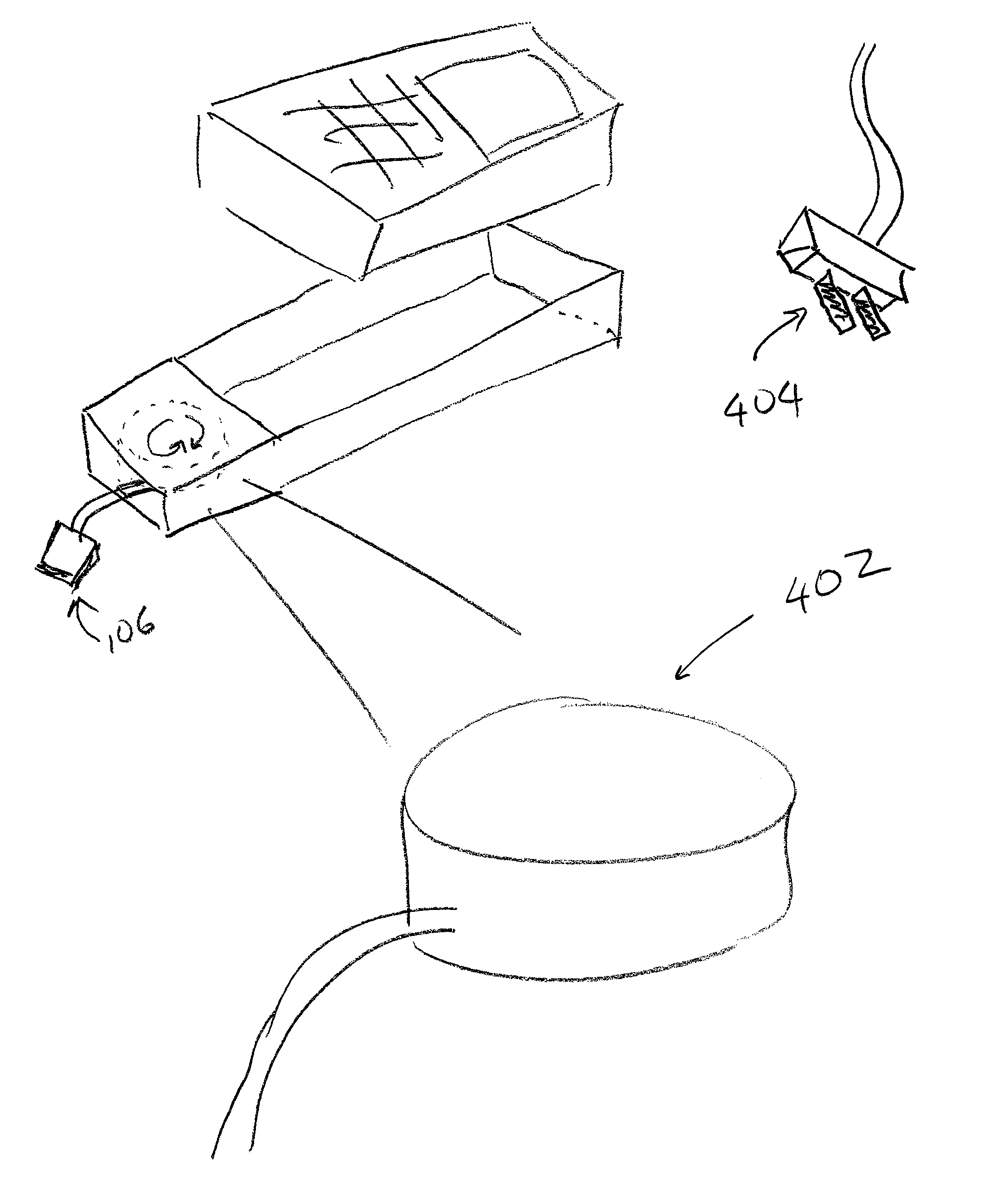
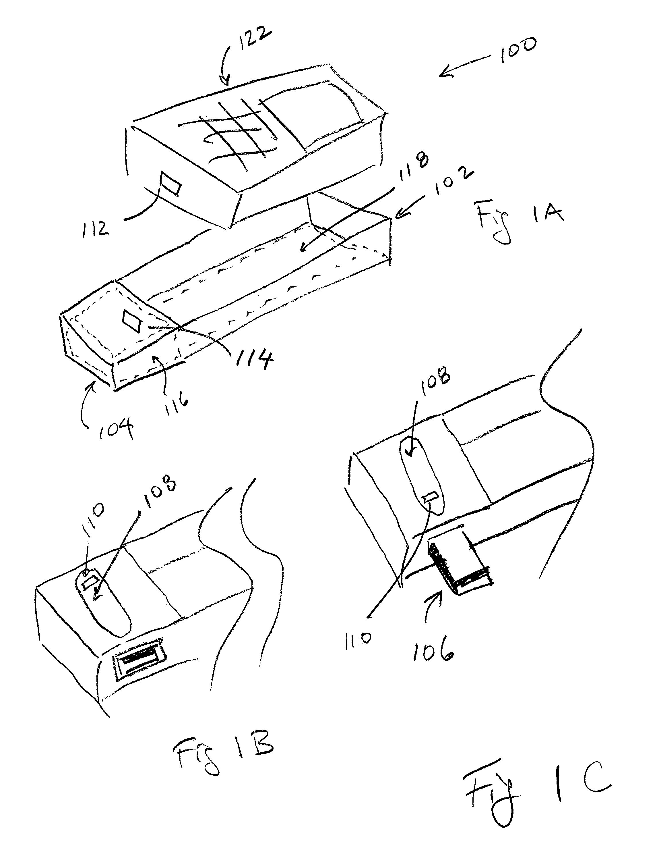
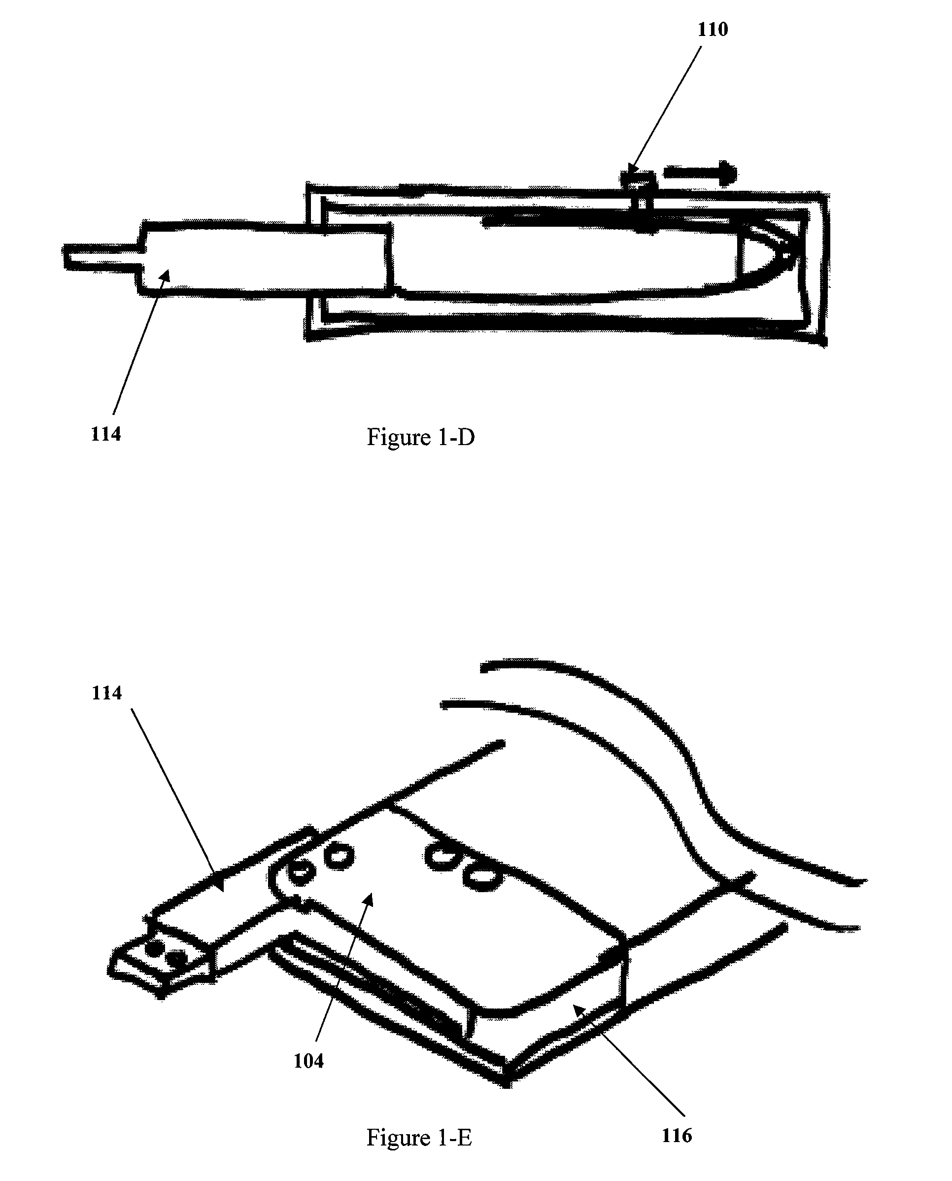
The present invention has several technical effects including an electronic device protective case that provides a snug fit around an electronic device and has one or more component cavities, internal electric connection means for interfacing with the electronic device, external electric connecting means for interfacing with external power sources, and electronic control circuitry means for interfacing with both the internal and external electric connecting means. The case is pliable and made of materials like silicone or leather. The invention also includes mechanical means to control the deployment of the external electronic connecting means such as a slidable mechanism, swinging mechanism, or spooling cable assembly. The electronic control circuitry means further comprise a current limiting circuitry, which can limit the current input to the electronic device. This invention provides an effective solution for protecting and powering electronic devices.

Problems solved by technology

Besides their bulk (given the propensity of devices to not require data interfacing via the cable, the extra shielding on these cables mean they are simply overbuilt), these cables constantly require winding and unwinding, which leads to internal conductor failure.

Method used


Image

  • Electronic device shield and connector case
  • Electronic device shield and connector case
  • Electronic device shield and connector case

Examples


Embodiment Construction

[0023]To provide an overall understanding of the invention, certain illustrative embodiments and examples will now be described. However, it will be understood by one of ordinary skill in the art that the same or equivalent functions and sequences may be accomplished by different embodiments that are also intended to be encompassed within the spirit and scope of the disclosure. The compositions, apparatuses, systems and / or methods described herein may be adapted and modified as is appropriate for the application being addressed and that those described herein may be employed in other suitable applications, and that such other additions and modifications will not depart from the scope hereof.

[0024]A fuller understanding of the nature and the objects of the present invention will be more apparent upon consideration of the following detailed description taken in connection with the accompanying drawings.

[0025]Referring to FIGS. 1A-1E we show an exemplary embodiment of the invention, a ...


PUM


Abstract

An electronic device protective case with a built-in capability to have a connector or cable that enables it to interface to power and communication sources without the need for a separate cable. The connector can be an AC connector for power, or a DC connector for power and / or signals, such as an universal serial bus (USB) connector or similar connector. The connector or cable can the move between a stowed position within the protective case housing and a deployed positions where it is external to said case.

Description

PATENTS CITED[0001]The following documents and references are incorporated by reference in their entirety, Morrison (U.S. Pat. No. 7,151,912), Bi (U.S. Pat. Appl. No. 2009 / 0128090), Bean et al (U.S. Pat. Appl. No. 2004 / 0036449), Groves et al (U.S. Pat. No. 6,402,546), Godovich (U.S. Pat. Appl. No. 2006 / 0267547), Jones, III et al (U.S. Pat. No. 6,379,178), Simon et al (U.S. Pat. Appl. No. 2009 / 0051312), Skowronski (U.S. Pat. No. 6,702,077) and Fan (U.S. Pat. No. 5,592,066).FIELD OF THE INVENTION[0002]The present invention relates to a shielding case for portable electronics devices, in particular to ones that house various connectors and cables in order to connect or power the device without the use of a separate cable.DESCRIPTION OF THE RELATED ART[0003]Most of us have a portable electronic device with wireless capabilities. These range from cellular Handsets and Smartphones (such as the iPhone, Android or other devices), Tablets (such as the iPad), eReaders (e.g. Nook, Kindle, Fire...

Claims


Application Information

Patent Timeline
IPC IPC(8): H01R13/72H01R13/44
CPCH01R13/72G06F1/16G06F1/1628
Inventor ZEOLLA, GIORGIO
Owner ZEOLLA GIORGIO
Learn More