
High throughput laser ablation processes and structures for forming contact holes in solar cells

a solar cell and laser ablation technology, applied in the field of solar cells, can solve the problems of increasing the complication of shunting on high-efficiency bcbj solar cells, and achieve the effect of improving the efficiency of shunting

Active Publication Date: 2014-04-08
MAXEON SOLAR PTE LTD
View PDF35 Cites 17 Cited by
  • Summary
  • Abstract
  • Description
  • Claims
  • Application Information

AI Technical Summary

Benefits of technology

[0009]These and other features of the present invention will be readily apparent to persons of ordinary skill in the art upon reading the entirety of this disclosure, which includes the accompanying drawings and claims.

Problems solved by technology

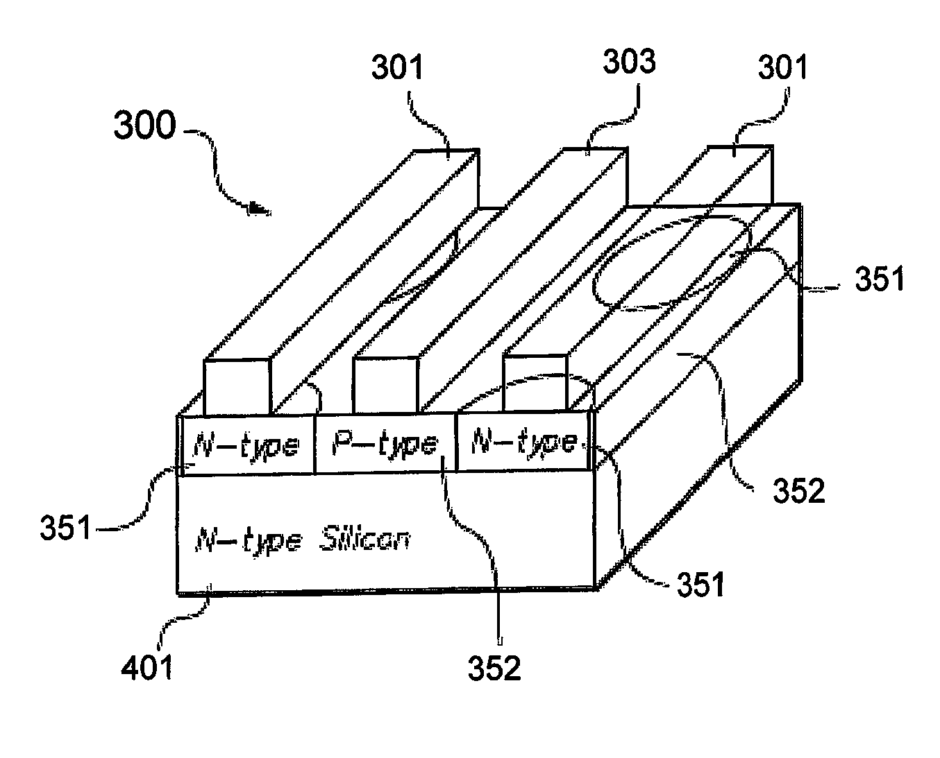
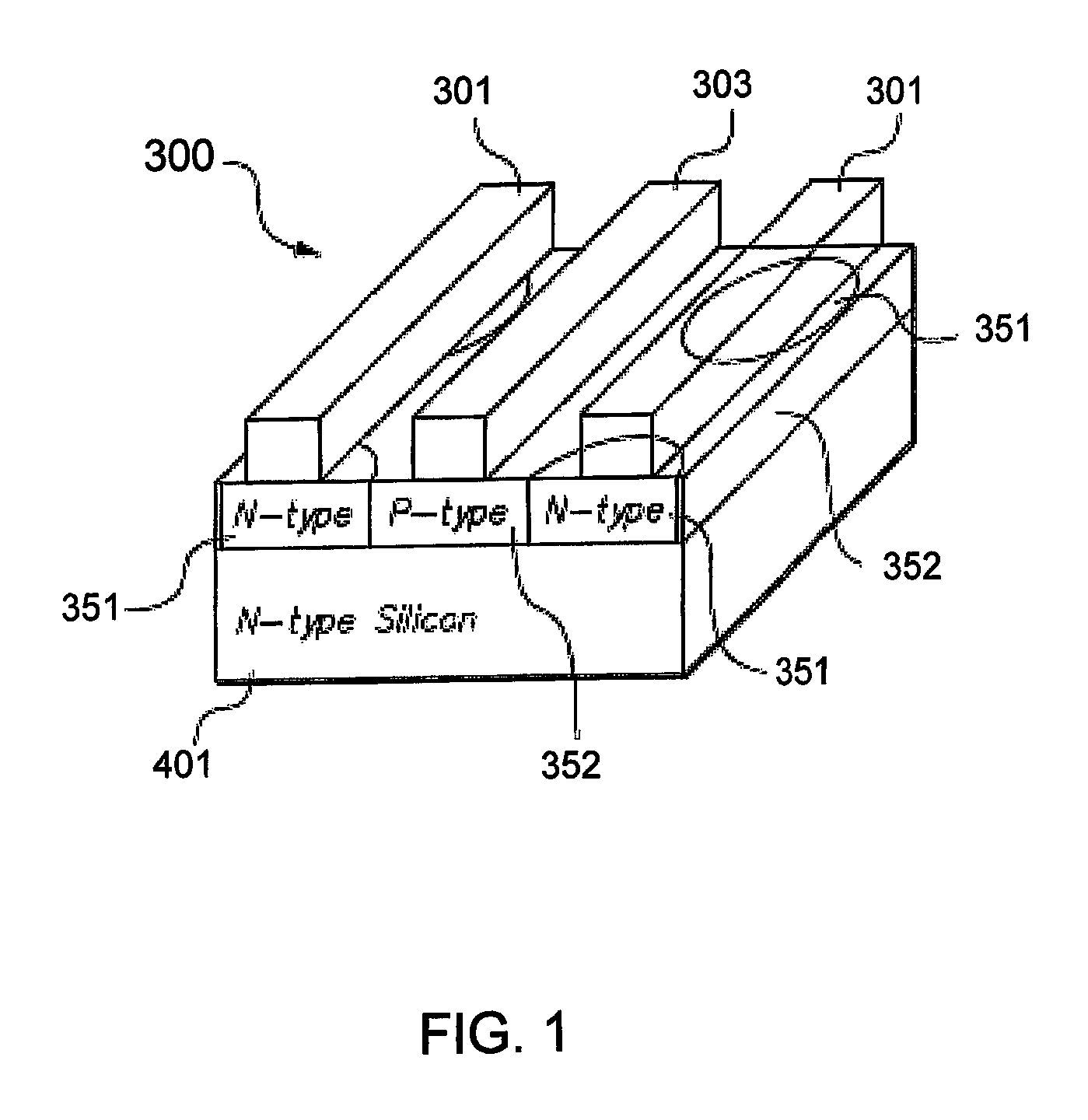
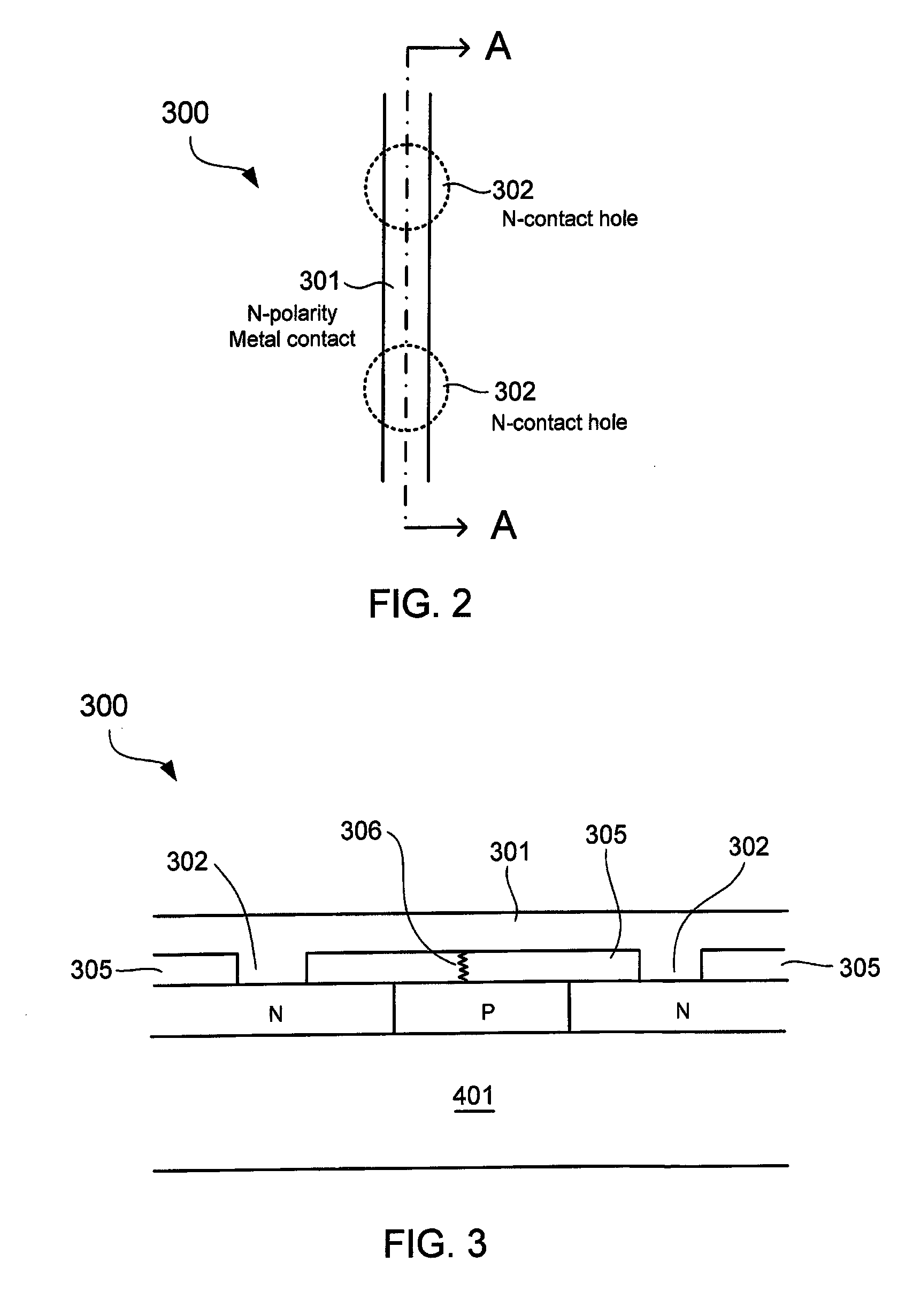
As is described within, an added complication of shunting on high-efficiency BCBJ solar cells may be prevalent when the cell architecture has metal of one polarity over diffusions of another polarity.

Method used


Image

  • High throughput laser ablation processes and structures for forming contact holes in solar cells
  • High throughput laser ablation processes and structures for forming contact holes in solar cells
  • High throughput laser ablation processes and structures for forming contact holes in solar cells

Examples


Embodiment Construction

[0032]In the present disclosure, numerous specific details are provided, such as examples of apparatus, processes, and structures, to provide a thorough understanding of embodiments of the invention. Persons of ordinary skill in the art will recognize, however, that the invention can be practiced without one or more of the specific details. In other instances, well-known details are not shown or described to avoid obscuring aspects of the invention.

[0033]In some high-efficiency solar cell designs, metal contacts for one polarity of diffusion region may run over an opposite polarity diffusion region (e.g., metal contact for an N-type diffusion region formed over a P-type diffusion region). In that solar cell design, it is critical that the interlayer dielectric that electrically insulates the metal contacts from the diffusion regions is free of defects. Otherwise, a metal contact of one polarity may electrically short to a diffusion region of opposite polarity through a defect in the...


PUM


Abstract

Contact holes of solar cells are formed by laser ablation to accommodate various solar cell designs. Throughput of the solar cell ablation process is improved by incorporating linear base diffusion regions with narrow width, for example as compared to an overlying metal contact. Throughput of the solar cell ablation process may also be improved by having contact holes to base diffusion regions that are perpendicular to contact holes to emitter diffusion regions. To allow for continuous laser scanning, a laser blocking layer may be located over an interlayer dielectric to prevent contact hole formation on certain regions, such as regions where a metal contact of one polarity may electrically shunt to a diffusion region of opposite polarity. In a hybrid design, a solar cell may have both linear and dotted base diffusion regions. An electro-optical modulator may be employed to allow for continuous laser scanning in dotted base diffusion designs.

Description

REFERENCES TO RELATED APPLICATION[0001]This application claims the benefit of U.S. Provisional Application No. 61 / 526,530, filed on Aug. 23, 2011, which is incorporated herein by reference in its entirety.TECHNICAL FIELD[0002]Embodiments of the subject matter described herein relate generally to solar cells. More particularly, embodiments of the subject matter relate to solar cell fabrication processes and structures.BACKGROUND[0003]Solar cells are well known devices for converting solar radiation to electrical energy. They may be fabricated on a semiconductor wafer using semiconductor processing technology. A solar cell includes P-type and N-type diffusion regions. Solar radiation impinging on the solar cell creates electrons and holes that migrate to the diffusion regions, thereby creating voltage differentials between the diffusion regions. In a backside contact, backside junction (BCBJ) solar cell, the P-type and N-type diffusion regions and the metal contacts coupled to them ar...

Claims


Application Information

Patent Timeline
Patent Type & Authority Patents(United States)
IPC IPC(8): H01L31/00H01L21/00
CPCH01L31/1804H01L31/022441H01L31/0682Y02E10/547Y02P70/50
Inventor KIM, TAESEOKHARLEY, GABRIELSMITH, DAVID D.COUSINS, PETER JOHN
Owner MAXEON SOLAR PTE LTD
Learn More