
System and method for backup communication using power over ethernet

a backup communication and power over ethernet technology, applied in data switching networks, frequency-division multiplexes, instruments, etc., can solve the problems and compromising the continuity of communication between patient rooms and nurses' stations. , to achieve the effect of increasing hardware and installation costs and time-consuming installation

Active Publication Date: 2014-04-08
JOHNSON CONTROLS FIRE PROTECTION LP +1
View PDF19 Cites 0 Cited by
  • Summary
  • Abstract
  • Description
  • Claims
  • Application Information

AI Technical Summary

Benefits of technology

This patent text talks about the problem with redundant Ethernet cabling solutions, which are expensive and require additional devices to connect the cables. These solutions also increase hardware and installation costs. The patent aims to solve this problem.

Problems solved by technology

As such, it is important that the devices be functional at all times. Where a portion of the communication network malfunctions, however, continued communication between patient rooms and nurses' stations can be compromised.
Such redundant Ethernet cabling solutions, however, suffer from the obvious disadvantage that the additional cables are costly and are time consuming to install.
This further increases hardware and installation costs.

Method used


Image

  • System and method for backup communication using power over ethernet
  • System and method for backup communication using power over ethernet
  • System and method for backup communication using power over ethernet

Examples


first embodiment

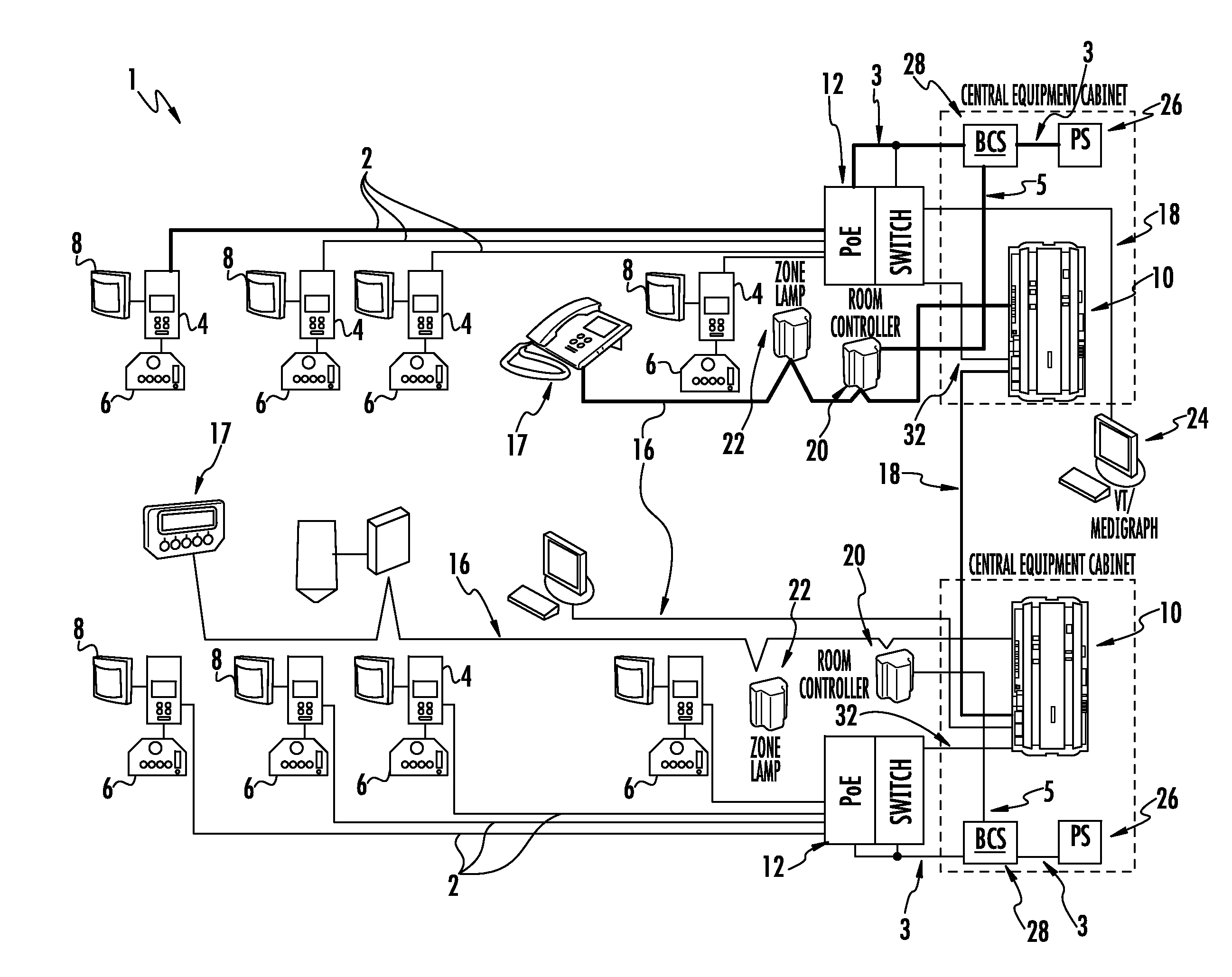
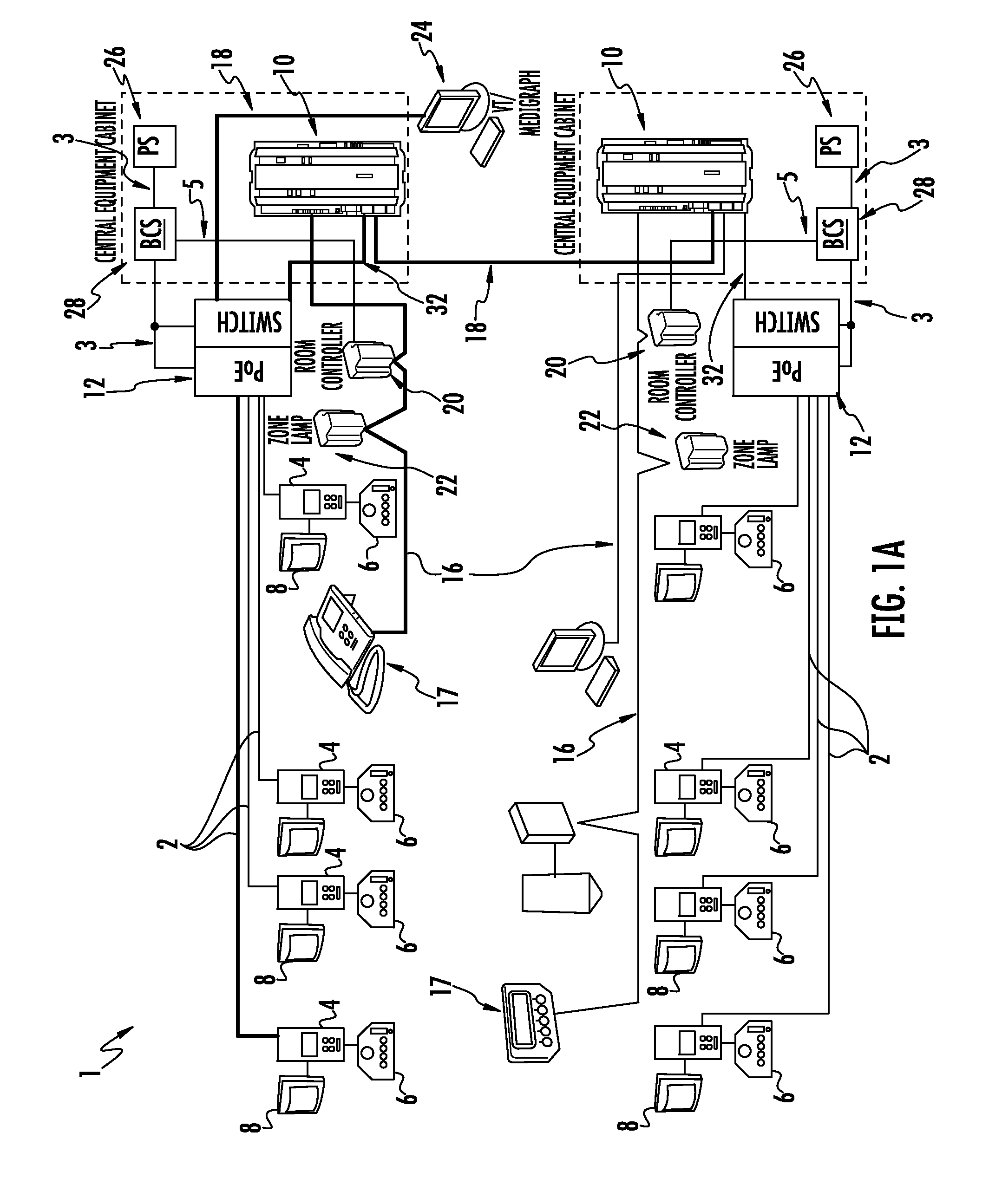
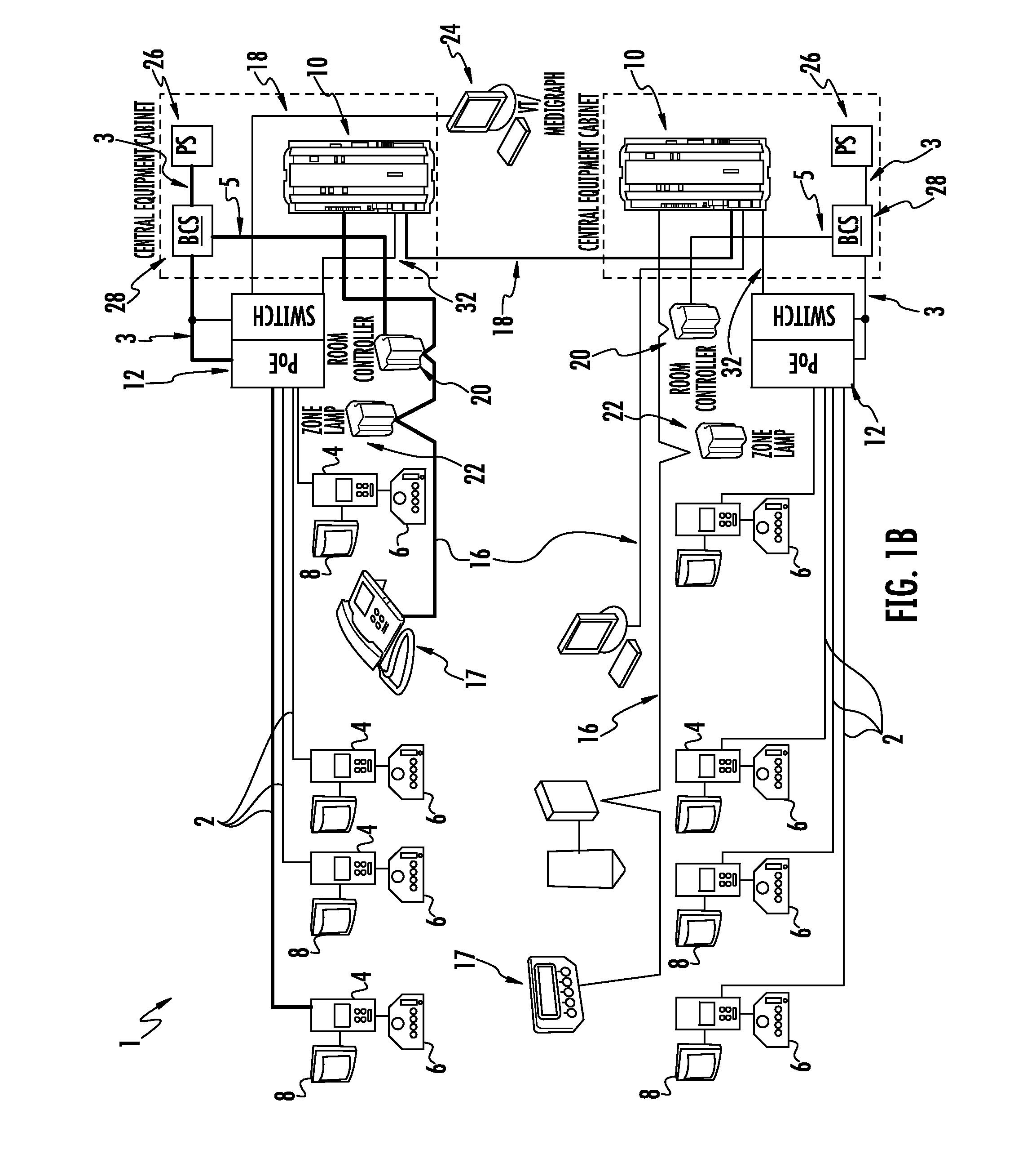
[0040]Referring now to FIG. 6, an exemplary method of operating the disclosed backup communication system 28 will be described. In one embodiment, the backup communication system 28 functionality is constantly “on,” even when the primary system is working. It will be appreciated, however, that such “constant on” functionality is not critical. For example, the room terminals 4 may be employed to recognize a failure in the gateway 10 and “turn on” the backup communication system 28. In one embodiment, the room terminals 4 could send a sync pulse to indicate that a failure of the gateway 10 has occurred. The backup communication system 28 could recognize the sync pulse and begin transmitting information in backup mode.

[0041]At step 100, a first call signal is sent from a call device, such as by a patient or nurse pressing a call button. The first call signal is sent on a power carrying conductor of an Ethernet cable. At step 110, the first call signal is received at a backup communicat...

second embodiment

[0042]Referring now to FIG. 7, a second exemplary method of operating the disclosed backup communication system 28 will be described. At step 200, a first call signal is sent from a call device to a monitoring device, which in one embodiment is a room controller. At step 210, the monitoring device receives the first signal. At step 220, the monitoring device sends a second call signal to a backup communication system (BCS), the second call signal being representative of the first call signal. At step 230, the second call signal is received by the BCS. At step 240, the BCS sends a third call signal to a patient room terminal, where the third call signal is sent on a power carrying conductor of an Ethernet cable. The third call signal representative of the first and second call signals. At step 250, the patient room terminal receives the third call signal and recognizes it as a message from the call device.

[0043]As used herein, an element or step recited in the singular and proceeded ...


PUM


Abstract

A system and method for providing backup communications using Power over Ethernet (PoE) are disclosed. A backup communication system (BCS) is provided as part of a networked (TCP / IP) hospital communication system. The BCS is coupled to a power line used to provide power to a PoE switch. When TCP / IP communications are interrupted, the BCS receives patient call signals from patient room terminals over a secondary communication mode of the power line, and transmits those call signals to a nurses' station. The call signals can be generated by coupling a pulse-coded AC signal onto the PoE wires, or by sending voltage coded data in one direction and current-coded data in the other direction. Different signals or signal levels can be used to distinguish normal patient calls, patient emergency calls, and code calls. Thus, basic communications can be achieved when TCP / IP are unavailable. Other embodiments are disclosed and claimed.

Description

FIELD OF THE DISCLOSURE[0001]The disclosure relates generally to systems and methods for communicating between components of a patient care system, and more particularly to a system and method for providing backup communications over Ethernet cabling when TCP / IP communications failures occur in a patient care system.BACKGROUND OF THE DISCLOSURE[0002]Hospitals typically include a variety of devices in patient rooms to enable the patient to communicate with a nurses' station. The hospital room communication devices may include a nurse call button, a microphone, a speaker, and the like. These devices enable the patient, or a nurse in the patient's room, to exchange a variety of emergency and non-emergency information with the nurses' station. These communications devices can be implemented as part of a larger network that services multiple rooms and floors of a hospital. Such networks may implement a TCP / IP protocol in which the hospital room devices are individually addressable, which...

Claims


Application Information

Patent Timeline
Patent Type & Authority Patents(United States)
IPC IPC(8): H04L12/26
CPCH04L12/10H04L12/2838
Inventor FARLEY, JOSEPH D.SCHUHMANN, WERNERZETTLER, HEINRICH
Owner JOHNSON CONTROLS FIRE PROTECTION LP
Learn More