
Ceiling system

a ceiling and system technology, applied in the field of ceiling systems, can solve the problems of time-consuming process prone to errors and undesired irregularities, significant work labour will additionally have to be spent, and the approach requires significantly more complicated and expensive runners, which are also more complicated to install

Pending Publication Date: 2022-08-04
SAINT GOBAIN ECOPHON
View PDF58 Cites 0 Cited by
  • Summary
  • Abstract
  • Description
  • Claims
  • Application Information

AI Technical Summary

Benefits of technology

The invention is a ceiling system that is easy to install and less prone to errors, even when using electric devices. It also provides a more robust system that can still function even if one of the power sources fails. This means that a room can still be lit up even if one of the electric devices malfunctions.

Problems solved by technology

This is a time consuming process prone to errors and undesired irregularities.
Further, if power consuming objects, such as lights, are to be introduced in a suspending ceiling, significant work labour will additionally have to be spent on preparing and connecting suitable wirings for the objects concerned.
This approach requires significantly more complicated and expensive runners which also are more complicated to install as compared to regular suspended ceilings.
The described system lacks flexibility in that the lighting modules must be attached directly under a grid profile and not in any location.
Moreover, the installation of the lighting system is time consuming and prone to installation errors since the lighting modules and connection modules must be properly connected to each other.
Also, power supplying wires will have to be installed which is time consuming and generally complicated.
This approach is however time consuming, expensive and does also significantly hamper the flexibility when it comes to positioning the power consuming objects in the suspended ceiling.

Method used


Image

  • Ceiling system
  • Ceiling system
  • Ceiling system

Examples


Embodiment Construction

[0069]The present invention will now be described more fully hereinafter with reference to the accompanying drawings, in which preferred embodiments of the invention are shown. This invention may, however, be embodied in many different forms and should not be construed as limited to the embodiments set forth herein; rather, these embodiments are provided for thoroughness and completeness, and fully convey the scope of the invention to the skilled person. Like reference numerals refer to like elements throughout the description.

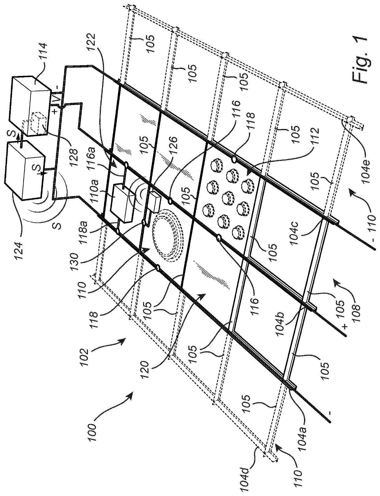
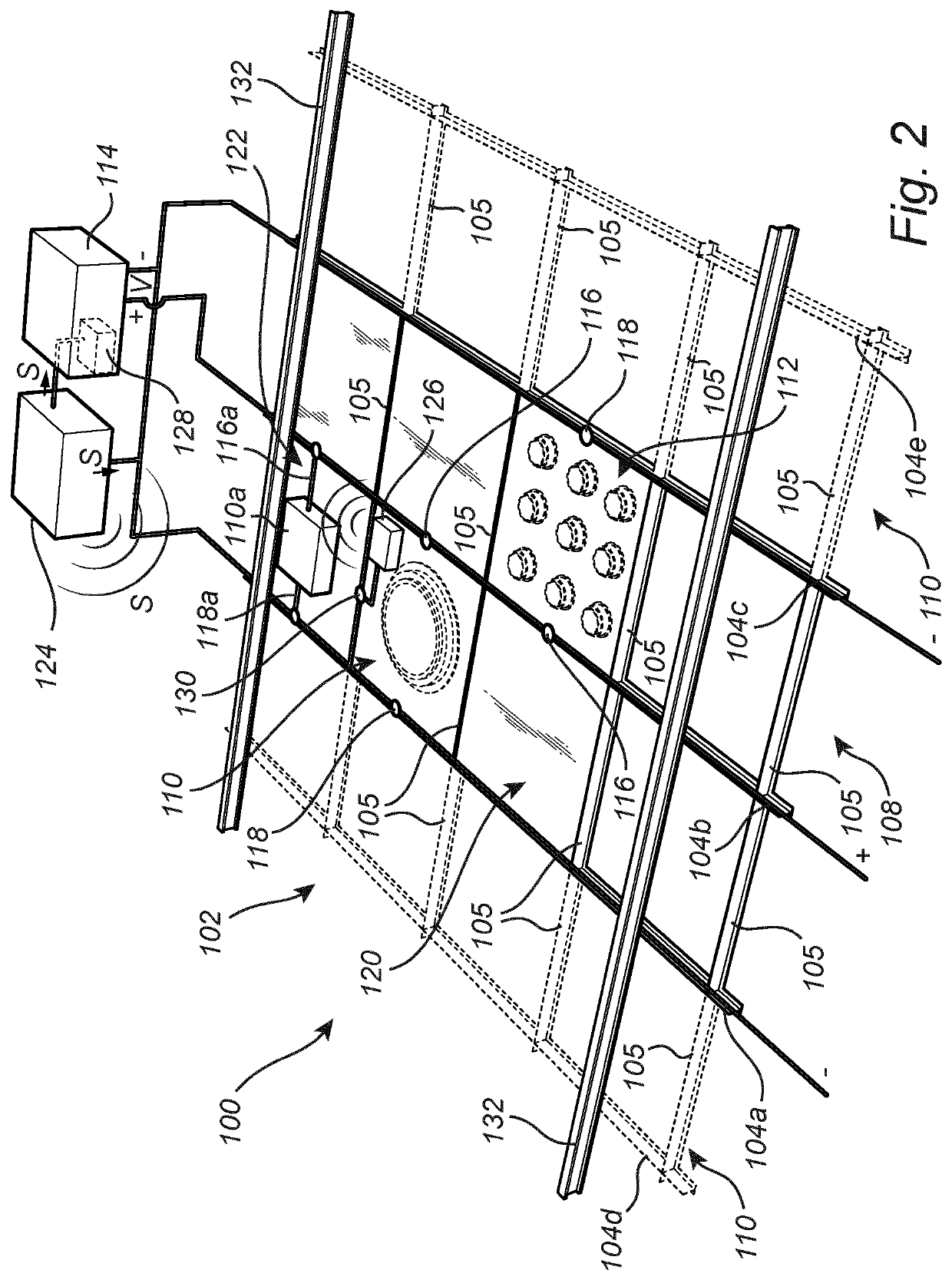
[0070]FIG. 1 is a schematic perspective view conceptually depicting a ceiling system 100. The ceiling system 100 is in form of a suspended ceiling system 100. The ceiling system 100 comprises a supporting structure 102. The supporting structure 102 comprises a plurality of main runners 104a-c extending side by side. For reasons of simplicity there are three main runners 104a-c illustrated in FIG. 1. In addition, two main runners 104d-e are shown in phantom to ...


PUM


Abstract

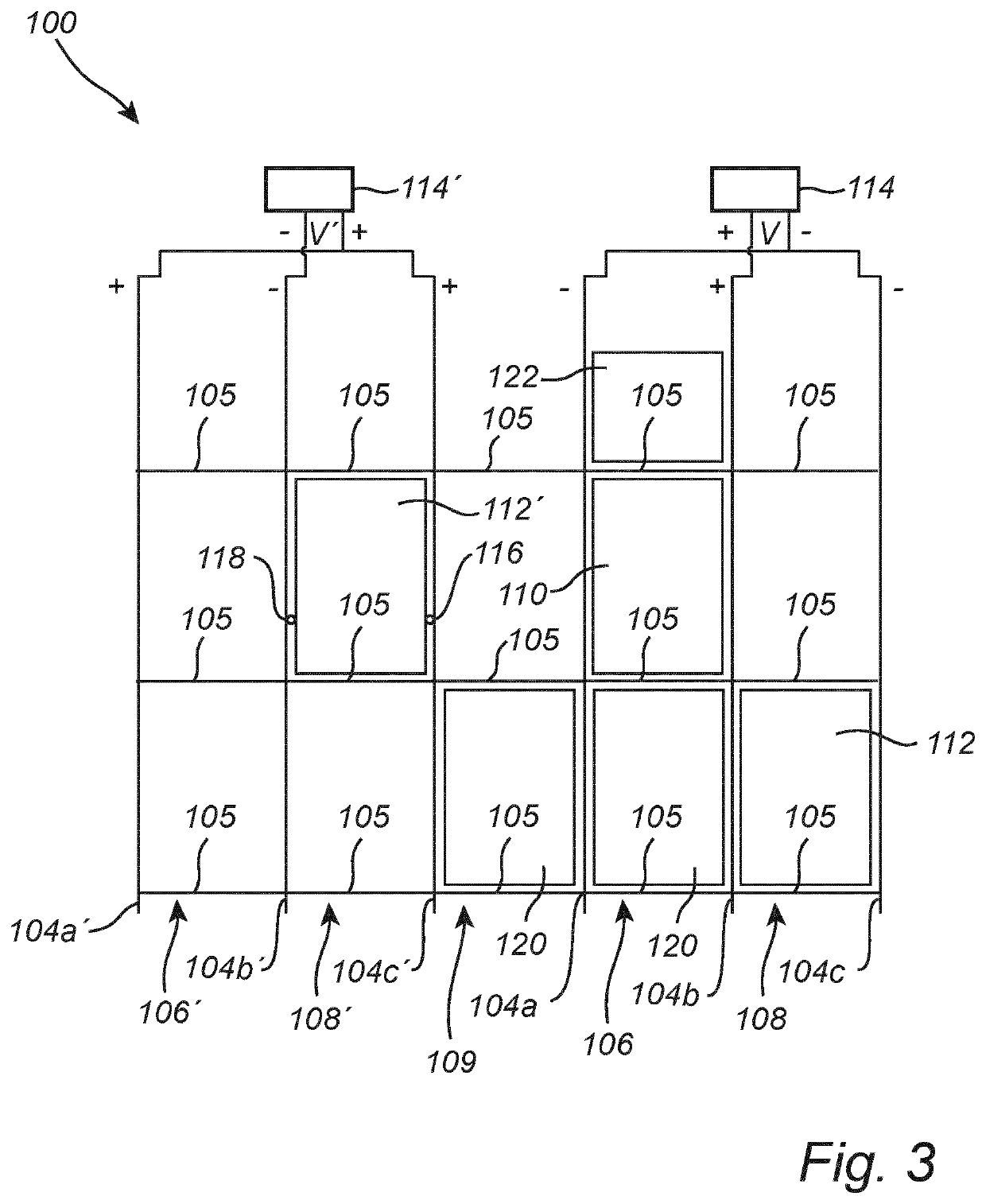
A ceiling system includes a supporting structure having a plurality of main runners made of an electrically conductive material. The main runners are arranged such that a first space is formed between at least one main runner and a first adjacent main runner and a second space is formed between the at least one main runner and a second adjacent main runner. An electric device is supported by the main runners and is arranged in the first or second space. A power source is arranged to apply an electric voltage between the main runners. The electric device includes connectors that are in electric contact with the main runners such that the electric device is powered by the applied electric voltage.

Description

FILED OF THE INVENTION[0001]The present invention generally relates to a ceiling system comprising a supporting structure comprising a plurality of main runners made of an electrically conductive material and an electric device supported by the main runners.BACKGROUND OF THE INVENTION[0002]A suspended ceiling system in a room or in another accommodation may serve a variety of purposes. One purpose of having a suspended ceiling system may be to conceal an underside of a space, such as another room, which is located above the room. Another purpose may be to provide improved noise absorption and / or noise attenuation in and outside of the room. The resulting plenum space located between the suspended ceiling and a main ceiling of the room may further be utilized to accommodate e.g. wiring, piping, as well as devices related to heating, ventilation and air condition.[0003]Typically, the suspended ceiling consists of a plurality of ceiling tiles which are fitted into a supporting grid of ...

Claims


Application Information

Patent Timeline
IPC IPC(8): E04B9/06
CPCE04B9/06E04B9/006E04B9/067E04B9/00
Inventor PERSSON, TORBJORNNILSSON, THOMASSTRANG, HAKAN
Owner SAINT GOBAIN ECOPHON
Learn More