Joint structure and robot

a joint structure and robot technology, applied in the field of robots, can solve the problems of low efficiency in the assembly of the joint structure, time-consuming servos, and difficulty in servo alignmen

Active Publication Date: 2019-11-26
UBTECH ROBOTICS CORP LTD
View PDF18 Cites 2 Cited by
  • Summary
  • Abstract
  • Description
  • Claims
  • Application Information

AI Technical Summary

Benefits of technology

[0003]Typically, robots include plural joint structures for connecting two components and enabling one of the two components to rotate with respect to the other. One problem with some conventional joint structures is that it is not easy for servos to align with other components during installation of the servos. The installation of servos is thus time-consuming, resulting in a low efficiency in the assembly of the joint structures.

Problems solved by technology

One problem with some conventional joint structures is that it is not easy for servos to align with other components during installation of the servos.
The installation of servos is thus time-consuming, resulting in a low efficiency in the assembly of the joint structures.

Method used


Image

  • Joint structure and robot
  • Joint structure and robot
  • Joint structure and robot

Examples


embodiment 1

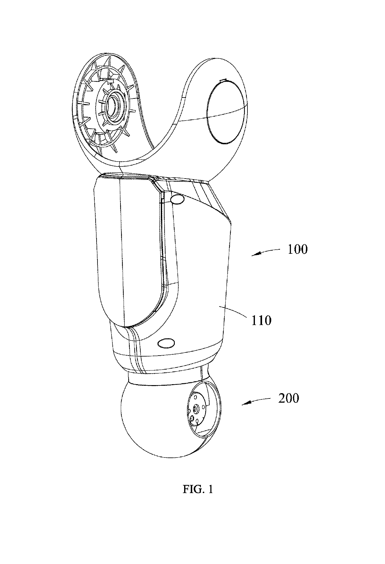
[0013]The present embodiment provides a joint structure that can be used to connect two adjacent robotic arms or to connect two adjacent robotic fingers. In the present embodiment, as an example, the joint structure is used to connect two adjacent robotic arms.

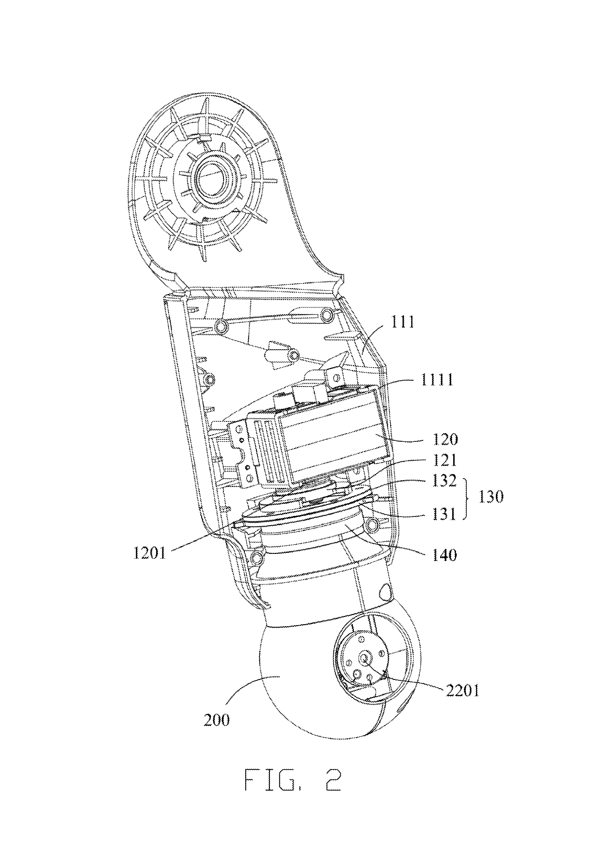
[0014]Referring to FIGS. 1-3, a joint structure includes a fixed member 100, a rotatable member 200 and a connection assembly 130. The fixed member 100 includes a housing 110 and a first servo 120 disposed within the housing 110. The connection assembly 130 is used to connect the rotatable member 200 to an output shaft 1201 of the first servo 120. The first servo 120 is sued to drive the rotatable member 200 to rotate.

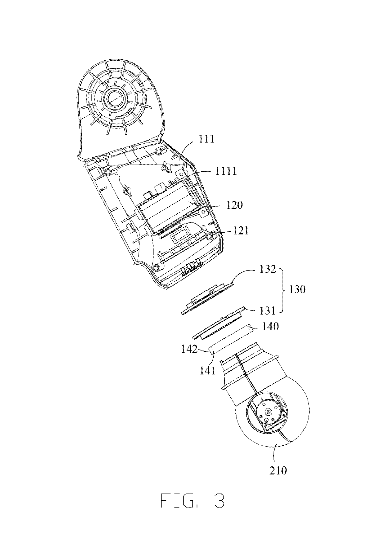
[0015]Referring to FIGS. 2 and 3, the connection assembly 130 includes a first flange 131 fixedly connected to the rotatable member 200 and a second flange 132 that is connected to the output shaft of the first servo 120. The second flange 132 is also connected to the first flange 131 via screws. The rotatable me...

embodiment 2

[0025]Referring to FIGS. 5-7, compared with the EMBODIMENT 1, the joint structure of the present embodiment further includes a movable member 300 connected to the rotatable member 200. The rotatable member 200 includes a casing 210 and a second servo 220 arranged within the casing 210. The output shaft 2201 of the second servo 220 is perpendicular to the output shaft 1201 of the first servo 120. The movable member 300 includes a shell 310 and a connection portion 320 connected to the shell 310 and the output shaft 2201 of the second servo 220. With the arrangement of the fixed member 100, the rotatable member 200 and the movable member 300, the joint structure has two degrees of freedom, thereby increasing the flexibility of the joint structure.

[0026]In one embodiment, referring to FIG. 6, the casing 210 includes a first casing 211 and a second casing 212 detachably connected to the first casing 211. The first casing 211 and the second casing 212 corporately define a second receivin...

embodiment 3

[0029]The present disclosure further provides a robot includes a joint structure of any one of the above embodiments, which will not be repeated here.


PUM


Abstract

A joint structure includes a fixed member, a rotatable member and a connection assembly. The fixed member includes a housing and a first servo disposed within the housing. The connection assembly is used to connect the rotatable member to an output shaft of the first servo. The connection assembly includes a first flange fixedly connected to the rotatable member and a second flange connected to the output shaft of the first servo and the first flange, and the rotatable member extend from within the housing to an outside of the housing.

Description

CROSS REFERENCE TO RELATED APPLICATIONS[0001]This application claims priority to Chinese Patent Application No. 201611251396.2, filed Dec. 30, 2016, which is hereby incorporated by reference herein as if set forth in its entirety.BACKGROUND1. Technical Field[0002]The present disclosure generally relates to the field of robotics, and particularly to a joint structure and a robot.2. Description of Related Art[0003]Typically, robots include plural joint structures for connecting two components and enabling one of the two components to rotate with respect to the other. One problem with some conventional joint structures is that it is not easy for servos to align with other components during installation of the servos. The installation of servos is thus time-consuming, resulting in a low efficiency in the assembly of the joint structures.BRIEF DESCRIPTION OF THE DRAWINGS[0004]Many aspects of the present embodiments can be better understood with reference to the following drawings. The co...

Claims


Application Information

Patent Timeline
Patent Type & Authority Patents(United States)
IPC IPC(8): B25J9/00B25J17/00B25J18/04
CPCB25J17/00B25J18/04B25J9/0009B25J17/0258
Inventor XIONG, YOUJUNZHAO, QI
Owner UBTECH ROBOTICS CORP LTD
Why Eureka
Try Eureka