Powered fish tape

a technology reeling device, which is applied in the field of powering fish tape, can solve the problems of destroying the central drive of such a reeling device, completely negating the normal operation of hand-held tools,

Inactive Publication Date: 2014-04-15
RIGGINS JOHN R
View PDF15 Cites 6 Cited by
  • Summary
  • Abstract
  • Description
  • Claims
  • Application Information

AI Technical Summary

Problems solved by technology

However, it has been shown that a central drive for such a reeling device is prone to breaking due to the large stresses that may come to bear when reeling in a long length of metal tape.
This feature also completely negates the normal operation of the hand-held tool.

Method used


Image

  • Powered fish tape
  • Powered fish tape
  • Powered fish tape

Examples


Embodiment Construction

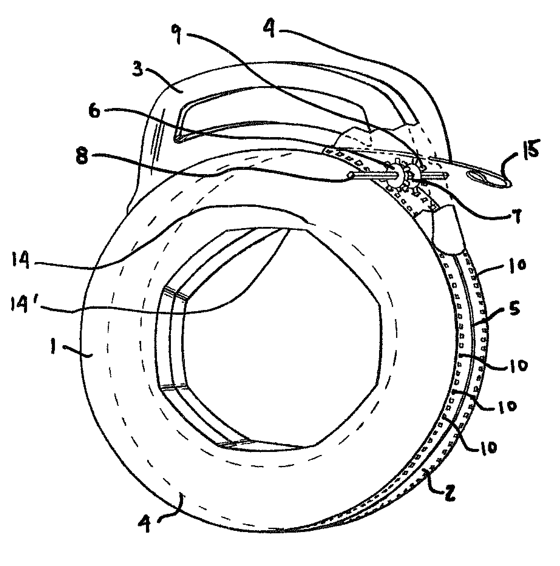
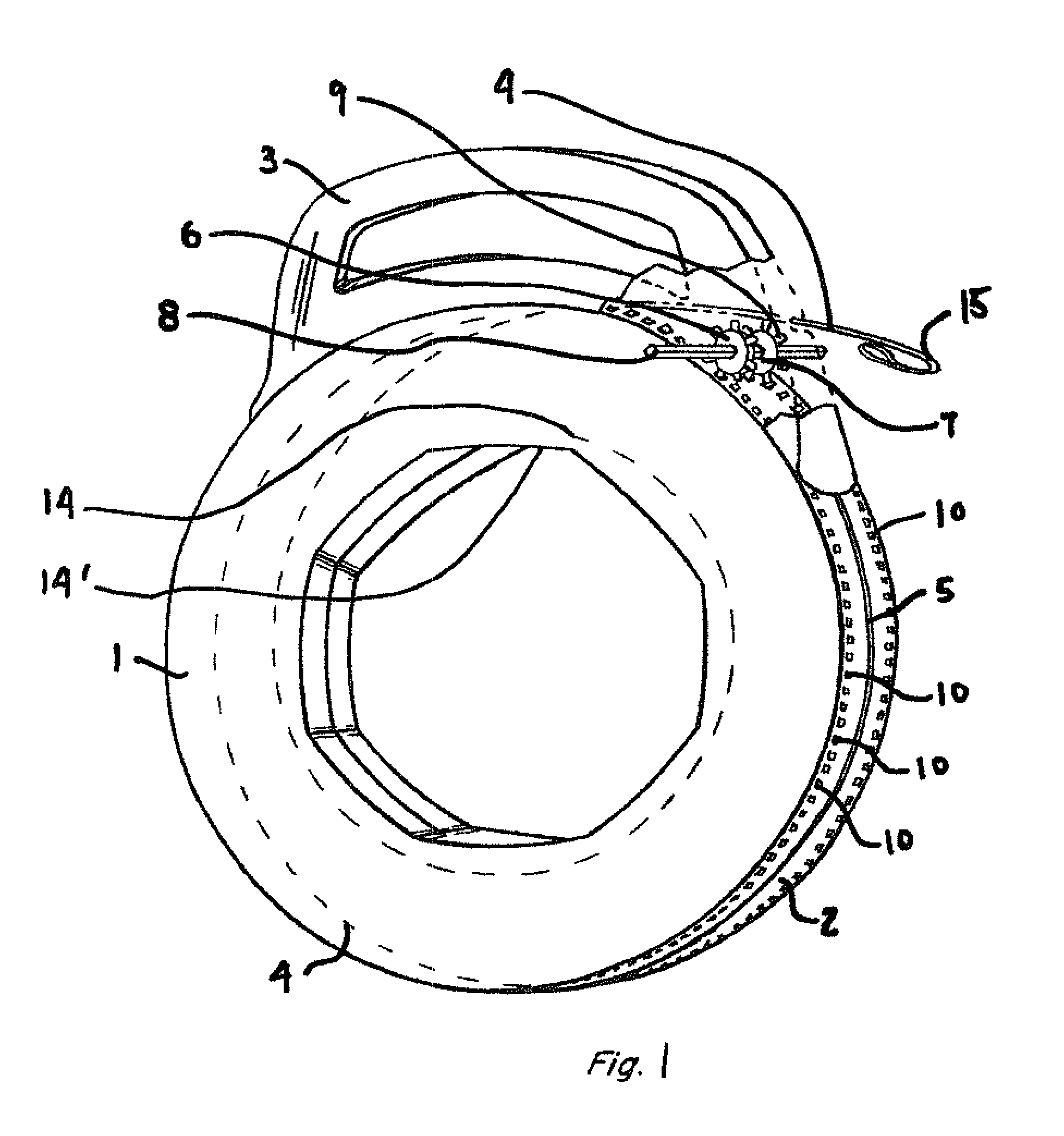
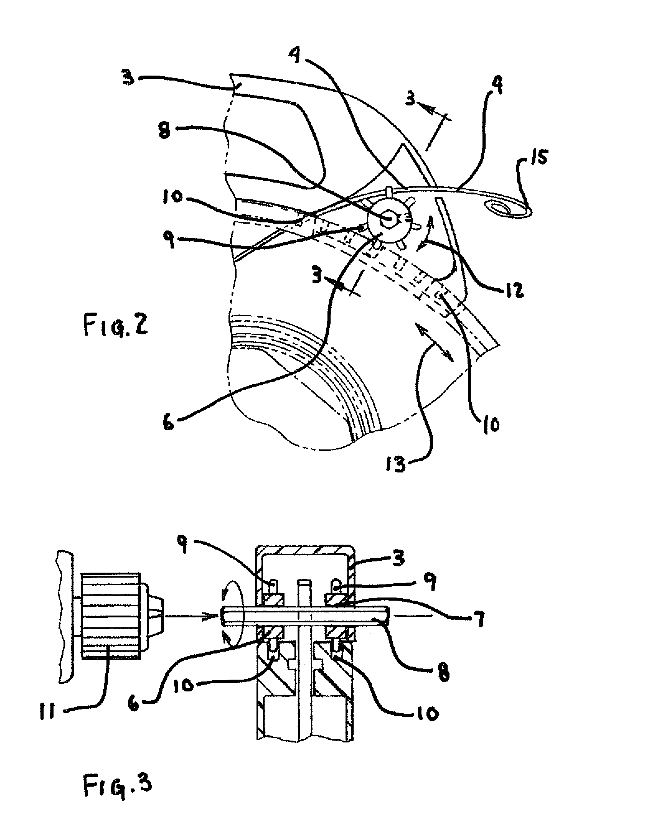
[0011]This invention is similar to other standard fish tape devices in general but has significant structural differences that enable a workman to use the device in conjunction with a drill or other powered device.

[0012]The device has an essentially cylindrical outer case, usually fabricated in front 1 and rear 2 sections. Each identical section is essentially cylindrical and hollow and adapted to receive a coiled metal fish tape as described below. These two sections are joined together in any convenient and workmanlike manner such as gluing or with screws attaching the two sections. The outer case has a central circumferential slot 5 along its edge as best shown in FIGS. 1 and 3.

[0013]The outer case has a handle 3 slidably engaged to the outer case such that the outer case rotates while the handle remains stationary and vice-versa. Normally, the lower part of the handle will have an outer flange which engages the inner sides of the outer case at the outer case circumferential slot...


PUM


Abstract

A metal fish tape for placing electrical wires in long conduit is coiled inside a cylindrical hollow case. The case has a slot all the way around it in the center of the edge of the cylindrical case. A handle is located in the slot. The case can rotate around its circumference when the handle is held stationary. Two sprocket gears connected to a hexagonal hub are attached to the handle. The gear teeth of the sprocket gears fit into a series of corresponding grooves that are located around the circumference of the case on each side of the case slot. The fish tape can still be used manually or the hub can be powered by a drill. When the handle (and sprocket gears) are held stationary, rotating the sprocket gears rotates the case and retracts the fish tape.

Description

BACKGROUND OF THE INVENTION[0001]This invention relates to the field of electrician's work. More particularly, a powered fish tape is presented that allows a workman to retract a fish tape using a power drill or the like.[0002]In the electrician's industry it is quite often necessary to place or “fish” electrical line through long lengths of conduit. In order to do this, one first pushes a narrow metal strip, or tape, through the conduit. The electric wire is then attached to the extended end of the metal tape and the metal tape is then retracted through the conduit, pulling the wire through the conduit as well.[0003]The common method of accomplishing this placement of the wire in the conduit is to use what is known in the industry as a fish tape. A good example of this type of device is found in the 2003 patent issued to Yates, U.S. Pat. No. 6,513,791. Yates describes the art and the well known reeling device. The Yates device utilizes a central hub to rotate the case while the han...

Claims


Application Information

Patent Timeline
Patent Type & Authority Patents(United States)
IPC IPC(8): H02G1/08
CPCH02G1/081
Inventor RIGGINS, JOHN, R.
Owner RIGGINS JOHN R
Why Eureka
Try Eureka