Shuffling machine

a shuffling machine and motor technology, applied in the field of automatic shuffling machines, can solve the problems of malfunction of the shuffling machine, increased power consumption,

Active Publication Date: 2014-04-15
TAIWAN FULGENT ENTERPRISE
View PDF17 Cites 89 Cited by
  • Summary
  • Abstract
  • Description
  • Claims
  • Application Information

AI Technical Summary

Problems solved by technology

However, the greater number of the motors means more power consumption.
Moreover, some shuffling machines have complex structure that may easily cause malfunction of the shuffling machine.

Method used


Image

  • Shuffling machine
  • Shuffling machine
  • Shuffling machine

Examples


Embodiment Construction

[0037]Reference will now be made in detail to the present examples of the invention, examples of which are illustrated in the accompanying drawings. Wherever possible, the same reference numbers will be used throughout the drawings to refer to the same or like parts.

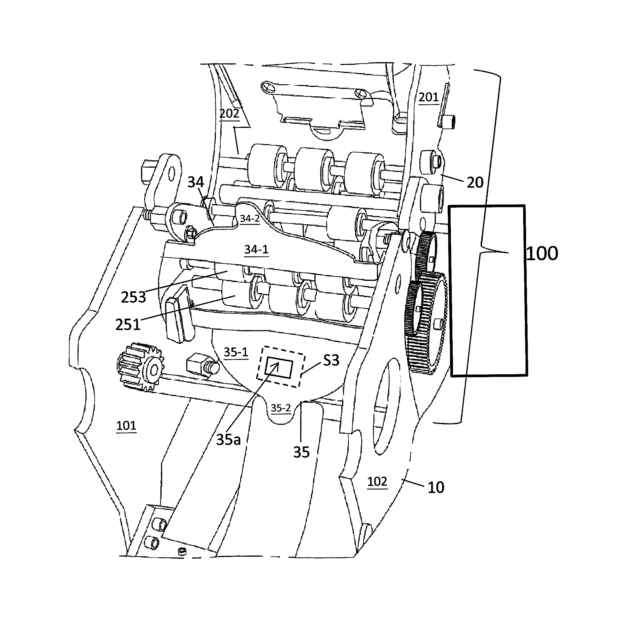
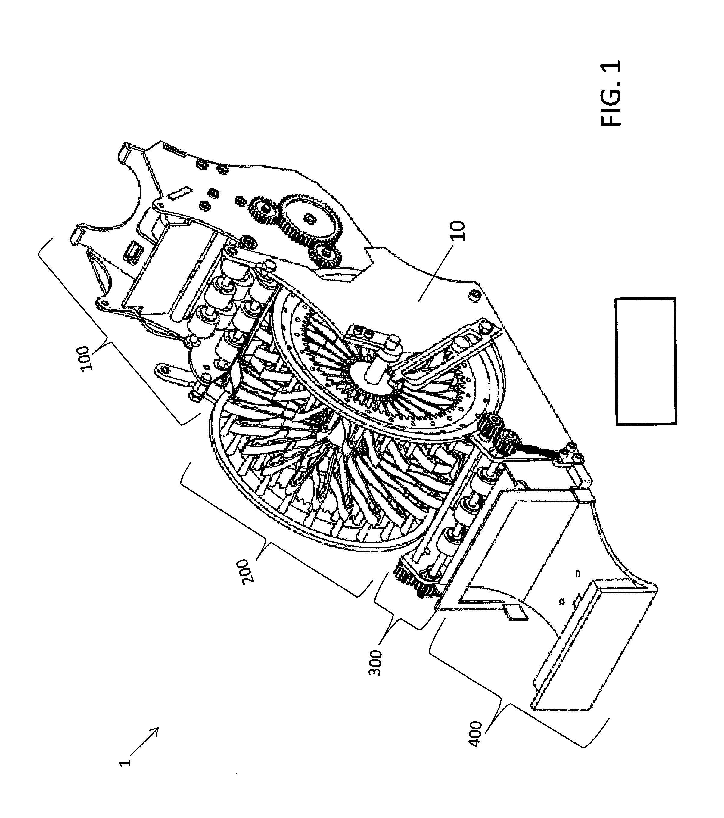
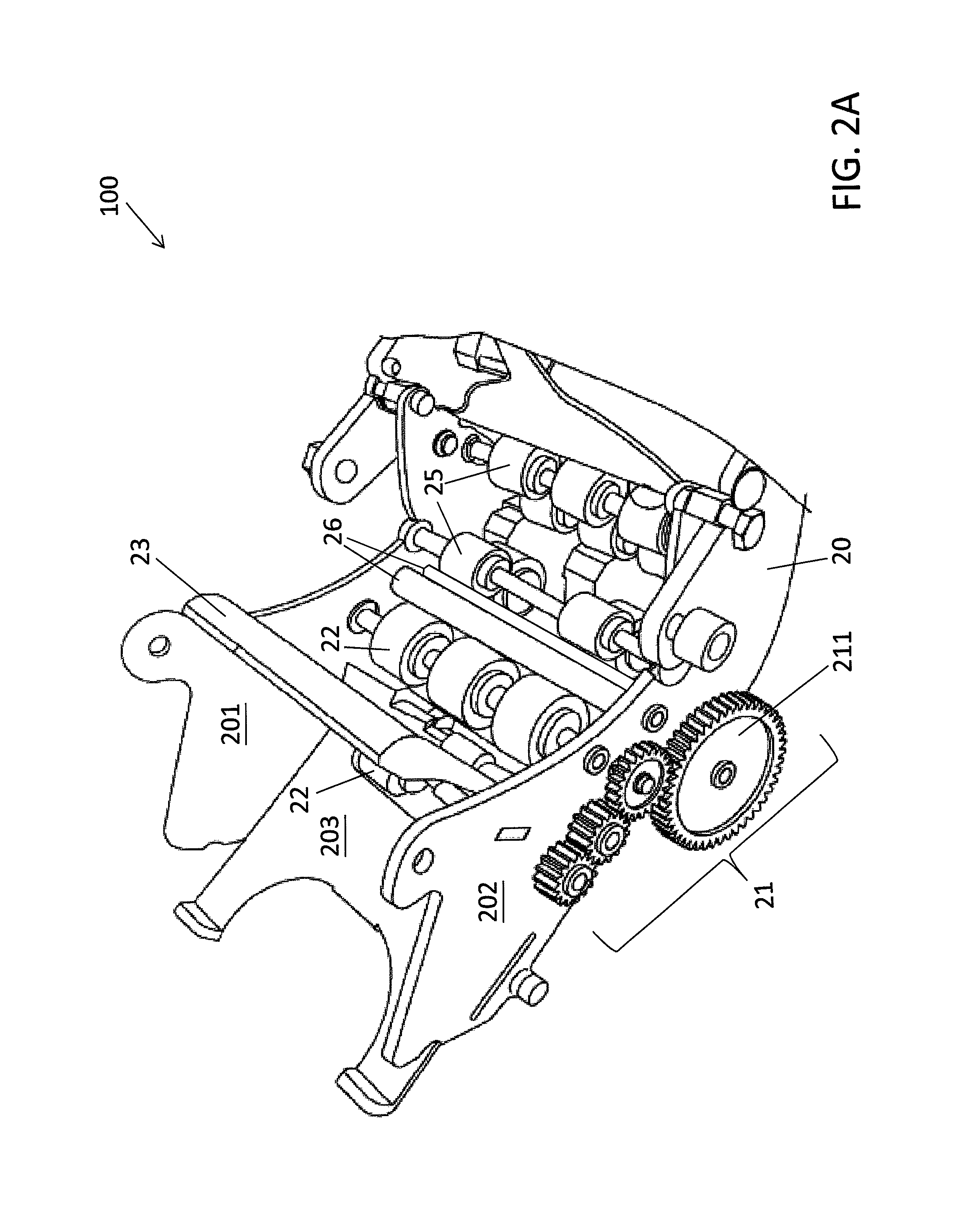
[0038]FIG. 1 is a perspective view of the shuffling machine 1 in accordance with an example of the present invention. Referring to FIG. 1, the shuffling machine 1 may include a card input device 100, a shuffling device 200, a card output device 300 and a card receiver 400. The shuffling machine 1 may further include a base 10 adapted to support the shuffling machine 1. The card input device 100 may be detachably mounted to the base 10 of the shuffling machine 1. Furthermore, the shuffling device 200 may be mounted to the base 10 adjacent to the card input device 100. Moreover, the card output device 300 may be securely mounted to the base 10 adjacent to the shuffling device 200 opposite to the card input device 100. In a...


PUM


Abstract

A shuffling device of a shuffling machine, the device comprising a base comprising a first and a second side walls, a wheel rotatably mounted between the first and second side walls of the base, the wheel comprising a first portion and a second portion each of which comprising a plurality of teeth formed on the inner rim a plurality pairs of retainers mounted to the first and second portions of the wheel, and an optical coder detachably mounted to the wheel, a motor detachably mounted on one of the first and second side walls of the base, and a gear coupled to and driven by the motor, wherein the gear is engaged with the teeth of one of the first and second portions of the wheel.

Description

BACKGROUND OF THE INVENTION[0001]The present invention generally relates to a shuffling machine, and more particularly, to an automatic shuffling machine.[0002]A general shuffling machine has a lot of motors to provide driving force to the mechanism resided in the shuffling machine. However, the greater number of the motors means more power consumption. Moreover, some shuffling machines have complex structure that may easily cause malfunction of the shuffling machine.[0003]It may therefore be desirable to have a shuffling machine that consumes less power and has a simpler structure.BRIEF SUMMARY OF THE INVENTION[0004]Examples of the present invention may provide a shuffling device of a shuffling machine, the device comprising a base comprising a first and a second side walls, a wheel rotatably mounted between the first and second side walls of the base, the wheel comprising a first portion and a second portion each of which comprising a plurality of teeth formed on the inner rim a p...

Claims


Application Information

Patent Timeline
Patent Type & Authority Patents(United States)
IPC IPC(8): A63F1/12
CPCA63F2009/2442A63F1/12A63F2009/2482
Inventor HO, CAI-SHIANG
Owner TAIWAN FULGENT ENTERPRISE
Why Eureka
Try Eureka