Crossbow

a technology of crossbows and bullpups, which is applied in the field of crossbows, can solve the problems of not having bullpup distances of more than a foot, and achieve the effect of increasing the surface area

Active Publication Date: 2014-04-22
FERADYNE OUTDOORS LLC
View PDF25 Cites 51 Cited by
  • Summary
  • Abstract
  • Description
  • Claims
  • Application Information

AI Technical Summary

Benefits of technology

[0023]The crossbow also provides a greater power stroke compared to crossbows of similar construction as the crossbow is provided with a bullpup stock that has a bullpup distance (distance from finger-pull mechanism to a string latch of the firing assembly) of more than six inches. Heretofore, crossbows were not outfitted with bullpup distances of more than six inches because the user would not then be able to utilize a sighting device mounted above the trigger box. However, as the beam provides for greater area to mount the sighting device than that provided for on prior art crossbows, the sighting device can be positioned forward of positions allowed for by prior art crossbows, thereby allowing the user to use the sighting device despite the crossbow having a bullpup distance of more than six inches. The bullpup distance of the crossbow also provides for a crossbow which does not negatively affect, and which may improve, the positioning of the center of gravity of the crossbow.
[0024]The crossbow further provides for a greater range of length of pull (distance from the string latch of the firing assembly to a butt end of the crossbow) of the crossbow such that the crossbow can be comfortably used by a greater range of individuals than can prior art crossbows.
[0025]A second preferred embodiment of the invention provides a crossbow having an elongated rearward member which adds to the rearward weight of the crossbow and, thus, necessarily moves the center of gravity of the crossbow rearward. When the crossbow is used, the elongated rearward member extends further rearward than does a butt member of the crossbow, which is typically positioned against a front of a user's torso at or proximate to a shoulder. The elongated rearward member is configured to extend past a user's shoulder and a bottom surface thereof is configured to rest or sit upon the user's shoulder, thereby providing the user with greater balance and support of the entire weight of the crossbow, thereby alleviating the amount of weight of the crossbow that must be supported by the hand on the grip of the crossbow.
[0026]A third preferred embodiment of the invention provides a crossbow having a bullpup distance of greater than eight inches, which allows for the forward weight of the crossbow to be reduced (and thus the rearward weight of the crossbow to be increased) such that the center of gravity of the crossbow will be moved rearwardly of the center of gravity of the first embodiment of the crossbow (when the crossbows have the same overall length), or which allows for the power stroke of the crossbow to be increased if the overall length of the crossbow is increased compared to the crossbow of the first embodiment.

Problems solved by technology

Heretofore, crossbows were not outfitted with bullpup distances of more than six inches because the user would not then be able to utilize a sighting device mounted above the trigger box.

Method used


Image

  • Crossbow
  • Crossbow
  • Crossbow

Examples


first embodiment

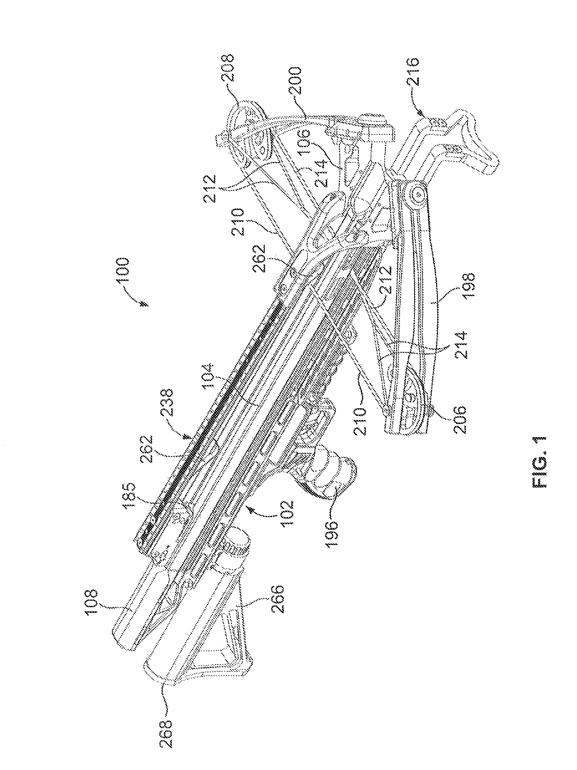
[0077]Attention is now directed to FIGS. 1-28 and the crossbow 100.

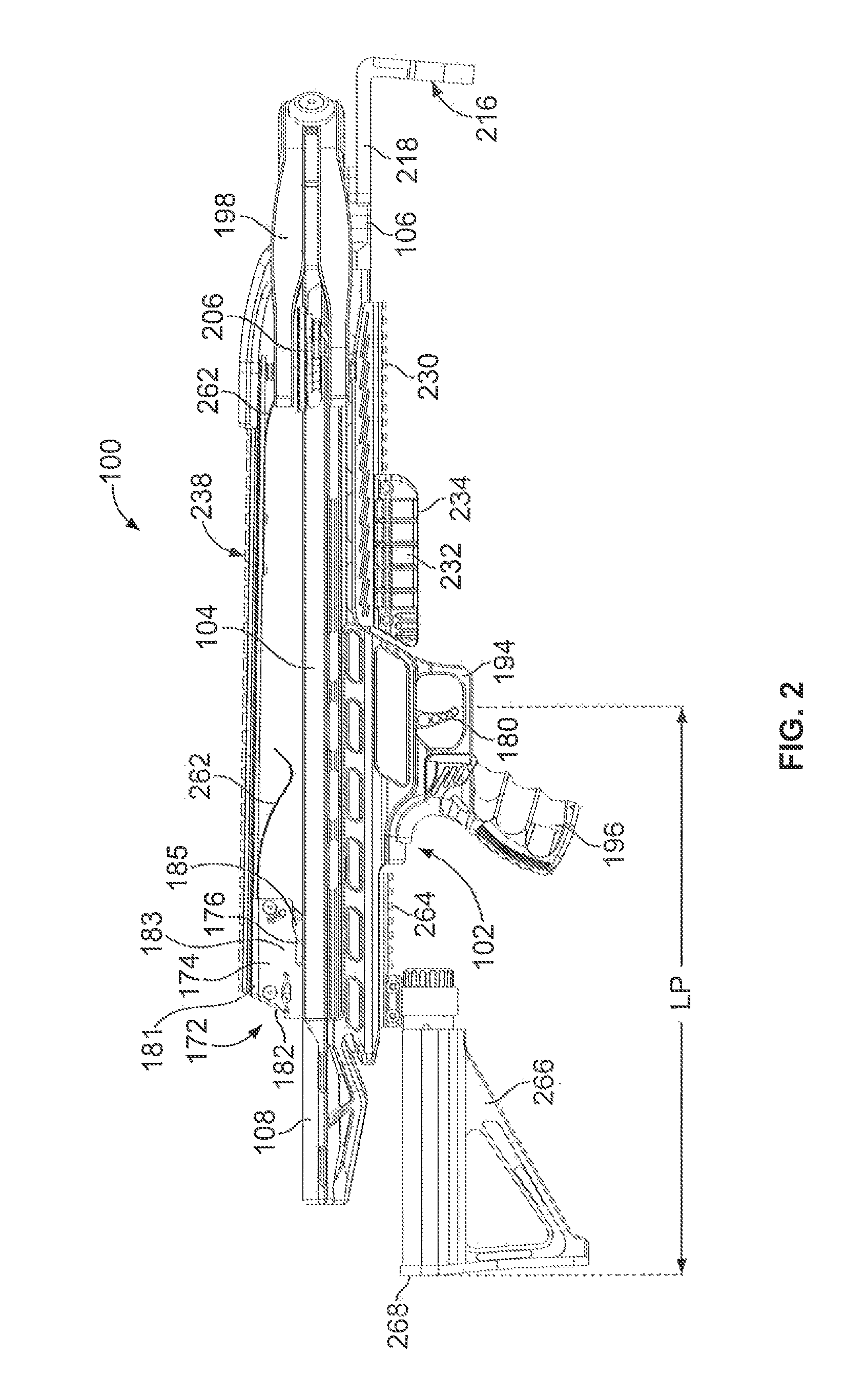
[0078]As best illustrated in FIGS. 1, 2 and 4, the crossbow 100 has a frame 102 which is preferably elongated. The frame 102 preferably includes a barrel 104, a riser 106 and a stock 108 which are all secured to one another.

[0079]The barrel 104 is best illustrated in FIGS. 8-12. The barrel 104 preferably is an elongated member having a forward end 110, an opposite rearward end 111, an upper portion 112 and a lower portion 113.

[0080]The lower portion 113 is generally tubular in configuration and defines a bottom wall 114, an upper wall 115, and right and left side walls 116, 117. The lower portion 113 is preferably hollow between the walls 114, 115, 116, 117, thereby defining an passageway 118 which extends therethrough from the forward end 110 to the rearward end 111. The bottom wall 114 has an opening 128 therethrough and the upper wall 115 has an opening 127 therethrough. The opening 127 of the upper wall 115 is pr...

second embodiment

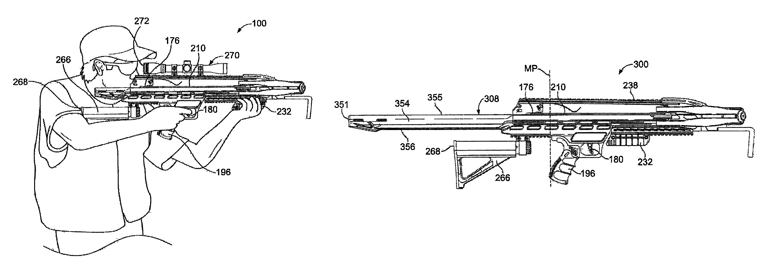
[0136]Attention is now directed to FIGS. 29 and 30 and the crossbow 300. The crossbow 300 is similar to the crossbow 100 and, therefore, only the structure of the crossbow 300 that varies from the crossbow 100 will be described in detail hereinbelow. All structure in the description of the crossbow 300 provided hereinbelow that is identical to the structure in the description of the crossbow 100 provided hereinabove will not be again described, but rather will be referenced with regard to the reference numerals in the one and two hundreds of the crossbow 100.

[0137]As illustrated in FIG. 29, the crossbow 300 is generally identical to the crossbow 100, with the exception that the stock 308 of the crossbow 300 is different in configuration from the stock 108 of the crossbow 100. More specifically, the stock 308 is preferably identical to the stock 108, with the exception that the stock 308 has an elongated rearward end portion 354 of the stock 308. The elongated rearward end portion 35...

third embodiment

[0150]Attention is now directed to FIGS. 31 and 32 and the crossbow 500. The crossbow 500 is similar to the crossbow 100 and, therefore, only the structure of the crossbow 500 that varies from the crossbow 100 will be described in detail hereinbelow. All structure in the description of the crossbow 500 provided hereinbelow that is identical to the structure in the description of the crossbow 100 provided hereinabove will not be again described, but rather will be referenced with regard to the reference numerals in the one and two hundreds of the crossbow 100.

[0151]The crossbow 500 has the same overall length as the crossbow 100 and is generally identical to the crossbow 100, with the following exceptions. The finger-pull mechanism 180 is positioned closer to a forward end 110 of the barrel 104. More specifically, the finger-pull mechanism is positioned at or forward of, a midway point (MP) between a forward and rearward end of the crossbow 500, As a result, the gripping member 196 i...


PUM


Abstract

A crossbow is provided which, in a first preferred embodiment, has a frame having a rear end, and a firing assembly and a butt member, each of which are associated with the frame. The firing assembly also has a finger-pull mechanism. The butt member has a rear end which is configured to abut a front of a shoulder of a user, and the butt member is positioned between the finger-pull mechanism and the rear end of the frame. In a second preferred embodiment, the crossbow has a frame having a rear end and first and second limbs secured to the frame. A bowstring extends between the first and second limbs and is configured to move between a forward rest position and a rearward cocked position. The rear end of the frame is configured to be positioned rearward of a front of a shoulder of a user.

Description

CROSS-REFERENCE AND INCORPORATION BY REFERENCE[0001]This patent application is a Continuation-in-Part of U.S. patent application Ser. No. 13 / 399,756, filed Feb. 17, 2012, and entitled “Accessory Mount For A Crossbow”. This patent application also claims the benefit of domestic priority of U.S. Provisional Application Ser. No. 61 / 711,860, filed Oct. 10, 2012, and entitled “Crossbow”. U.S. patent application Ser. No. 13 / 399,756 and U.S. Provisional Patent Application Ser. No. 61 / 711,860 are hereby incorporated by reference in their entireties.FIELD OF THE INVENTION[0002]The invention relates to crossbows. More particularly, the invention relates to crossbows which provide more area for mounting accessories thereto, which provide an increased power stroke without increasing a forward weight of the crossbow, and which provide better balance.BACKGROUND OF THE INVENTION[0003]The use of crossbows for hunting and target practice has increased in recent years. For some people, such as those ...

Claims


Application Information

Patent Timeline
Patent Type & Authority Patents(United States)
IPC IPC(8): F41B5/12
CPCF41B5/1442F41B5/12F41B5/1403F41B5/123
Inventor BIAFORE, JR., JOHN J.PESTRUE, JEFFREY ALLAN
Owner FERADYNE OUTDOORS LLC
Why Eureka
Try Eureka