
Method and apparatus for managing oxygen generating system

Active Publication Date: 2014-04-22
HVLPO2
View PDF12 Cites 13 Cited by
  • Summary
  • Abstract
  • Description
  • Claims
  • Application Information

AI Technical Summary

Benefits of technology

The apparatus and method described in this patent involve managing an oxygen generating system. It includes a control box with an oil-less air compressor to receive and compress oxygen from multiple banks of oxygen generators. The control box also has one or more controller devices to control power circuits for the oxygen generators and the oil-less air compressor. The controller devices are programmed to switch the circuits based on pressure from the oxygen storage tank. The technical effects include efficiently producing and delivering oxygen to the customer's demand, optimizing system performance, and reducing downtime for maintenance.

Problems solved by technology

Oxygen generators (also known as oxygen concentrators) on the market fail to provide the necessary pressure and / or volume required by larger glass torches used for working with large borosilicate glass (“boro”) pieces.
Only very expensive larger systems (such as systems for hospitals and universities) provide the necessary pressure and / or volume of oxygen for working with large borosilicate glass pieces with larger glass torches.
Relying on K-tanks is expensive.
Other problems associated with bottled gas include transport and storage hazards, availability, waiting for tank delivery, running out of oxygen mid-project, or dangers associated with changing oxygen tanks mid-project.
Currently there is no cost efficient oxygen generator system capable of producing a constant source of oxygen for use at sufficient oxygen flow and pressure; additionally, there are no oxygen generating systems which can be used with nominal 110 volt outlets without overloading a residential circuit breaker.

Method used


Image

  • Method and apparatus for managing oxygen generating system
  • Method and apparatus for managing oxygen generating system
  • Method and apparatus for managing oxygen generating system

Examples


Embodiment Construction

[0025]Reference will now be made in detail to the subject matter disclosed, which is illustrated in the accompanying drawings. The scope of the invention is limited only by the claims; numerous alternatives, modifications, and equivalents are encompassed. For the purpose of clarity, technical material that is known in the technical fields related to the embodiments has not been described in detail to avoid unnecessarily obscuring the description.

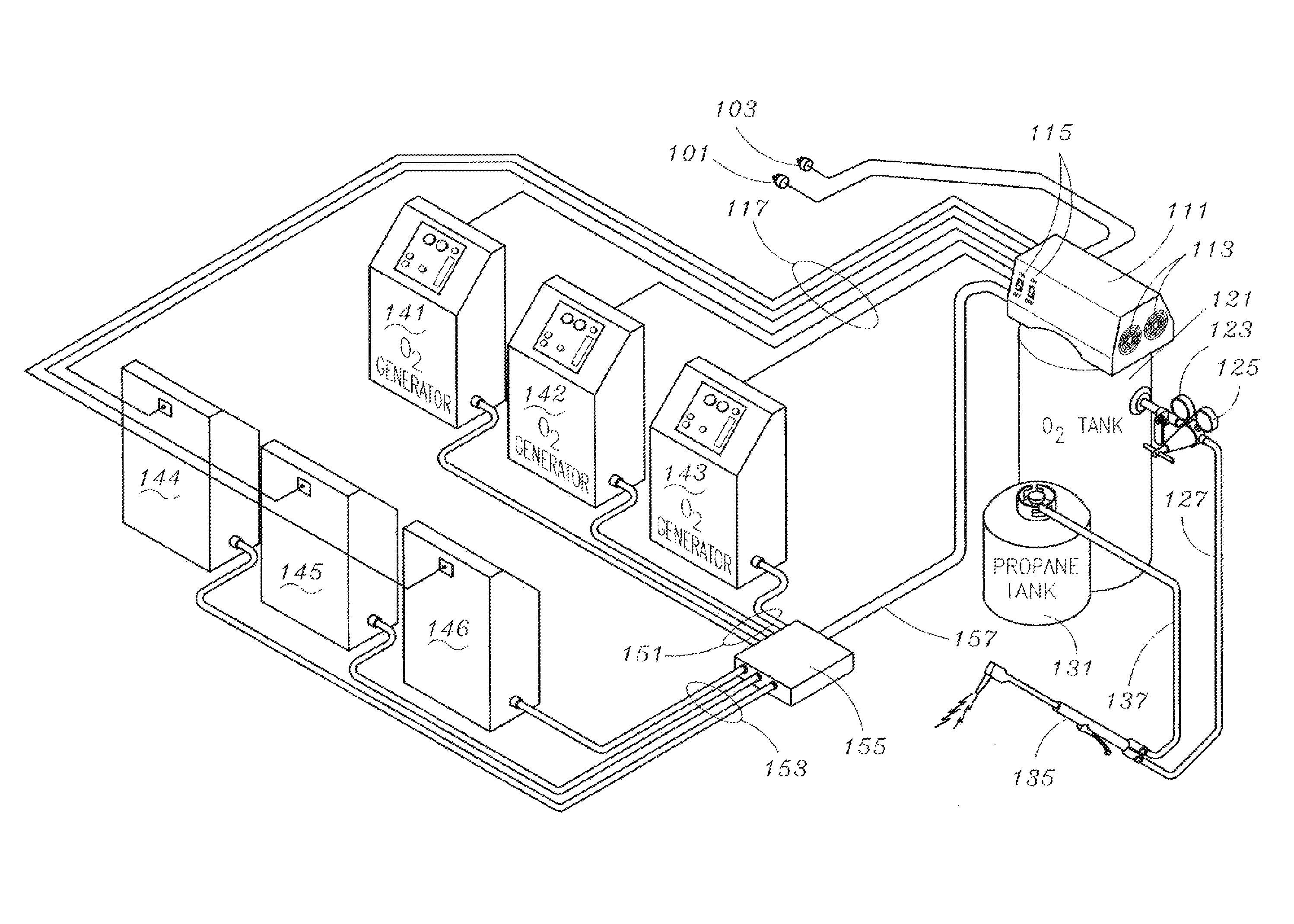
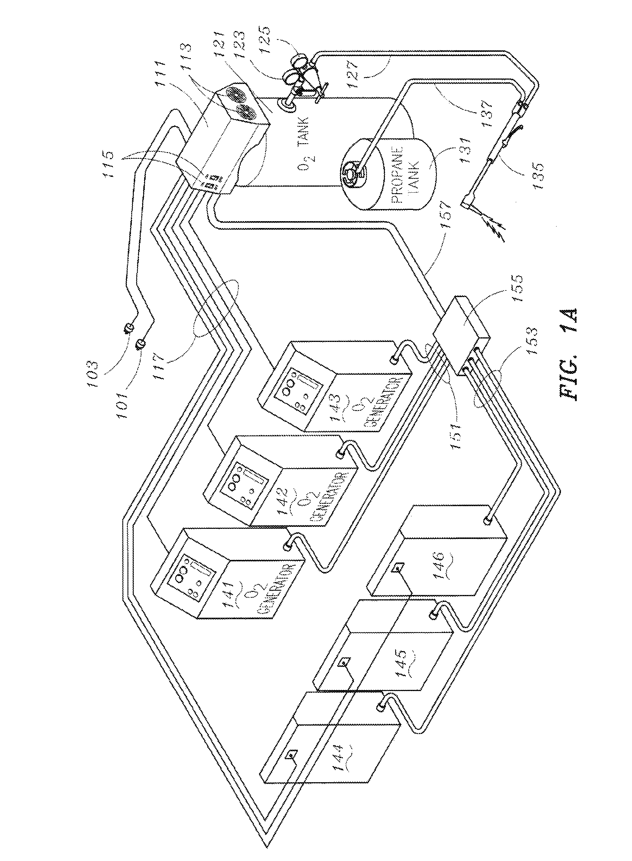
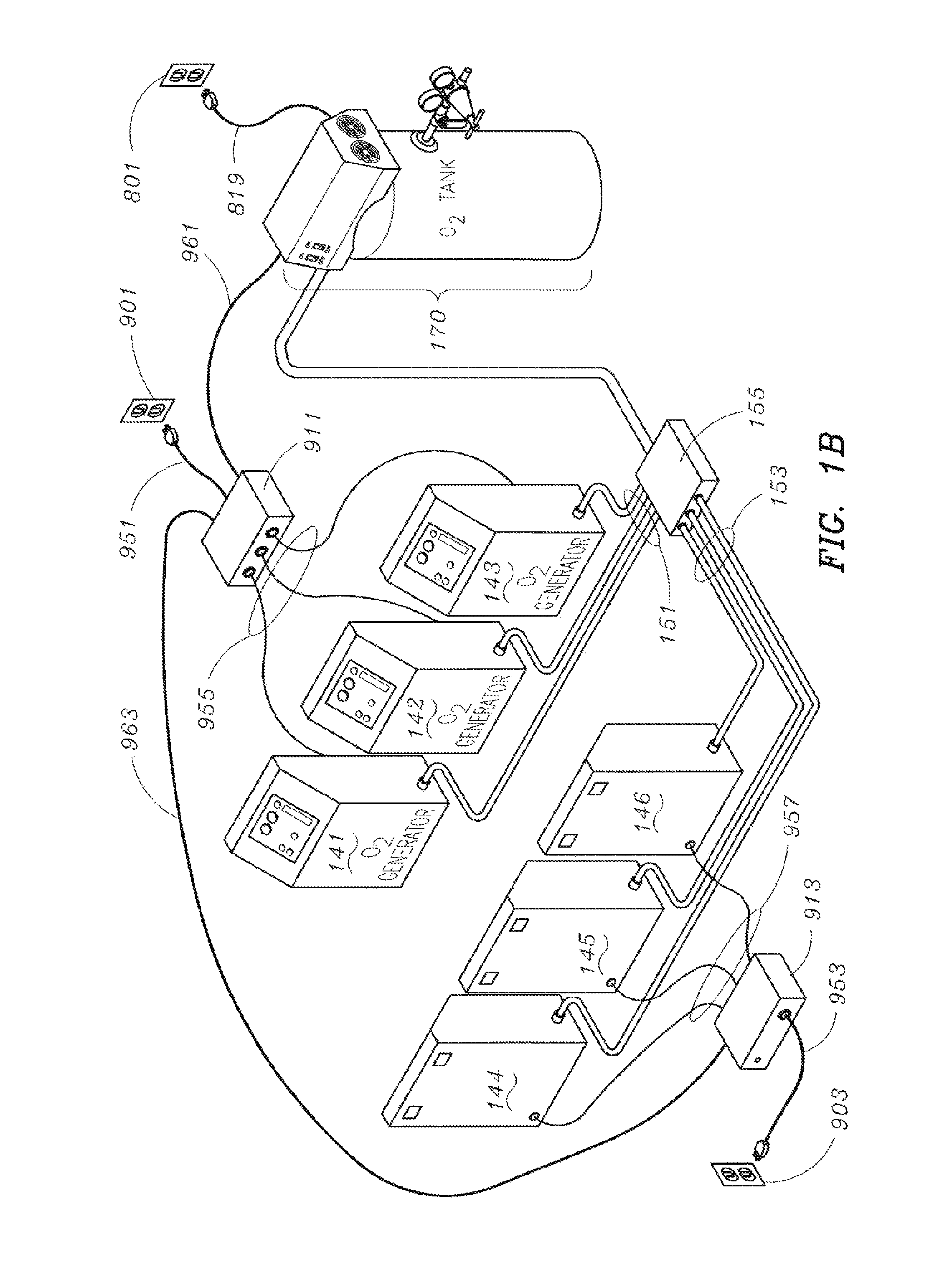
[0026]Embodiments of the invention may include an oxygen generating system, one or more components of the oxygen generating system, and methods of managing or controlling the oxygen generating system. The oxygen generating system may include a plurality of oxygen generators, a control box, an oxygen storage tank, and a vacuum pump compressor. Embodiments of the invention may further include the demodulation of a modular oxygen generating system into a plurality of independent oxygen generating systems; similarly, embodiments of the invention...


PUM

PropertyMeasurementUnit
Pressureaaaaaaaaaa
Pressureaaaaaaaaaa
Poweraaaaaaaaaa

Abstract

Apparatus and method for managing an oxygen generating system configured for supplying a sustained flow of oxygen, which may include a control box. The control box may include an oil-less air compressor configured to pump the oxygen to an oxygen storage tank from at least two banks of at least one oxygen generator. The control box may include or be connected to a pressure sensor associated with the oxygen storage tank. The control box may further include one or more controller devices configured to control at least two circuits for providing power to the at least two banks of at least one oxygen generator. The one or more controller devices may be configured to switch on or off each bank of oxygen generators in response to particular threshold pressures associated with the storage tank. The one or more controller devices may also be configured to control the oil-less air compressor.

Description

CROSS-REFERENCE TO RELATED APPLICATIONS[0001]The present application claims the benefit under 35 U.S.C. §119(e) of U.S. Provisional Application Ser. No. 61 / 583,051 filed Jan. 4, 2012; U.S. Provisional Application Ser. No. 61 / 583,051 is herein incorporated by reference in its entirety.FIELD OF THE INVENTION[0002]The present invention is directed generally toward systems, devices, controls, or methods for oxygen generation, oxygen storage, and / or oxygen supply configured to supply sustained high oxygen flow output or high oxygen output volumes.BACKGROUND OF THE INVENTION[0003]A continuous high-flow oxygen supply is critical for torch glass artists who use surface mix glass torches. Surface mix glass torches mix propane and oxygen creating a controlled flame in the temperature range of approximately 2,500 and 3,000 Fahrenheit. Glass torches typically need a constant supply of fairly pure oxygen (90-95% pure) at 20 to 30 pounds per square inch (psi) depending upon the model of the glass...

Claims


Application Information

Patent Timeline
IPC IPC(8): B01D53/00
CPCB01D2259/4533B01D53/047B01D2259/40007B01D2256/12B01D53/00A61M16/101B01D53/053B01D53/02C01B13/02F04D25/06G05D27/02C01B13/0248G05B19/4155G05B2219/37371
Inventor FRIEDMAN, THOMAS D.ELLENWOOD, ERICKORNBLUH, MARC
Owner HVLPO2
Features
  • Generate Ideas
  • Intellectual Property
  • Life Sciences
  • Materials
  • Tech Scout
  • Unparalleled Data Quality
  • Higher Quality Content
  • 60% Fewer Hallucinations
Learn More