
Micro-unmanned aerial vehicle deployment system

a technology of unmanned aerial vehicles and deployment systems, which is applied in the direction of micro-sized aircraft, transportation and packaging, weapons, etc., can solve the problems of limited range and endurance of muavs, and achieve the effect of extending the range of operation of a weapon system deploying muavs

Inactive Publication Date: 2014-04-29
THE UNITED STATES OF AMERICA AS REPRESENTED BY THE SECRETARY OF THE NAVY
View PDF13 Cites 71 Cited by
  • Summary
  • Abstract
  • Description
  • Claims
  • Application Information

AI Technical Summary

Benefits of technology

The present invention aims to improve the performance of a weapon system that uses drones. The invention provides means to extend the range of operation of the system, which means that the drones can operate at longer ranges and with greater precision. This makes the weapon system more effective and reliable.

Problems solved by technology

Although the MUAV serves well in its intended purpose, one serious limitation of the MUAV is its limited range and endurance.

Method used


Image

  • Micro-unmanned aerial vehicle deployment system
  • Micro-unmanned aerial vehicle deployment system
  • Micro-unmanned aerial vehicle deployment system

Examples


Embodiment Construction

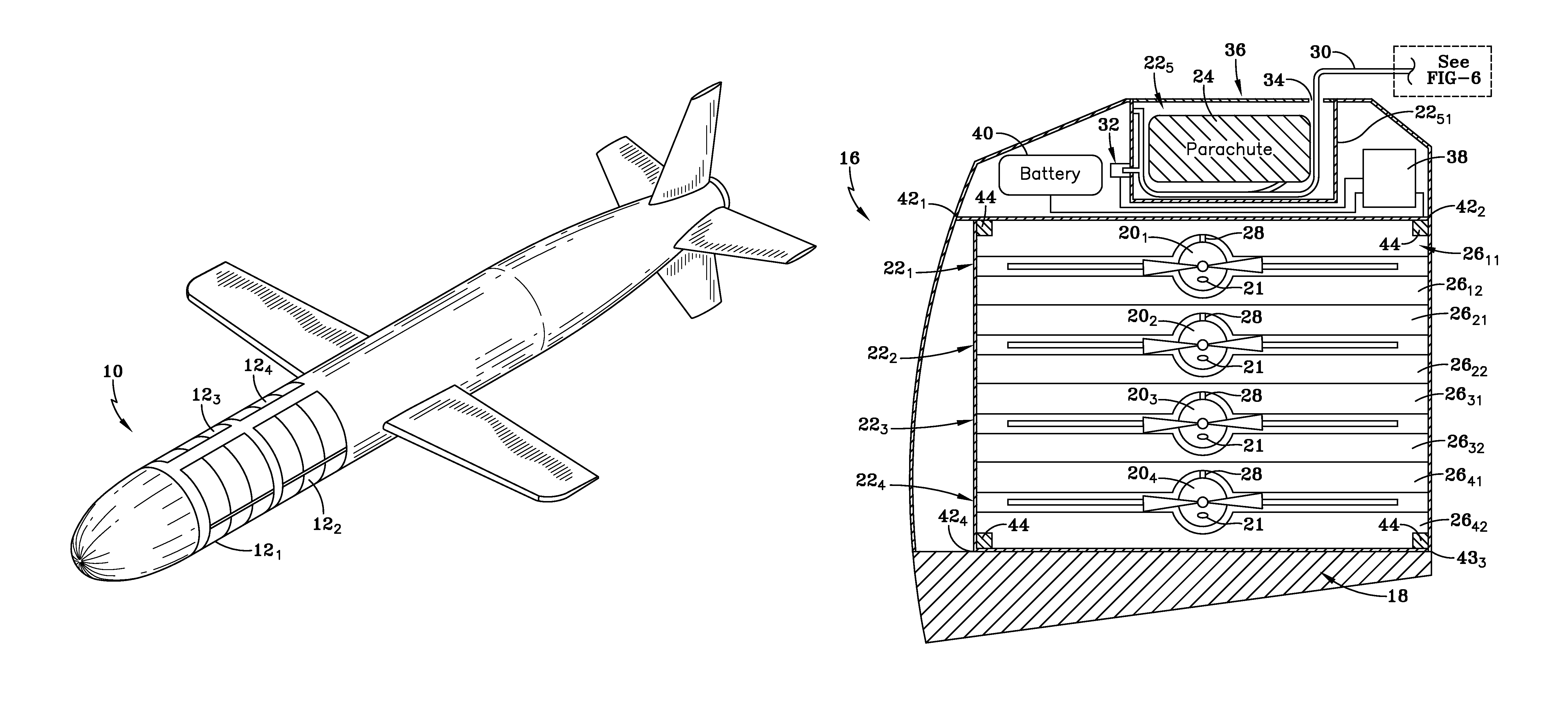
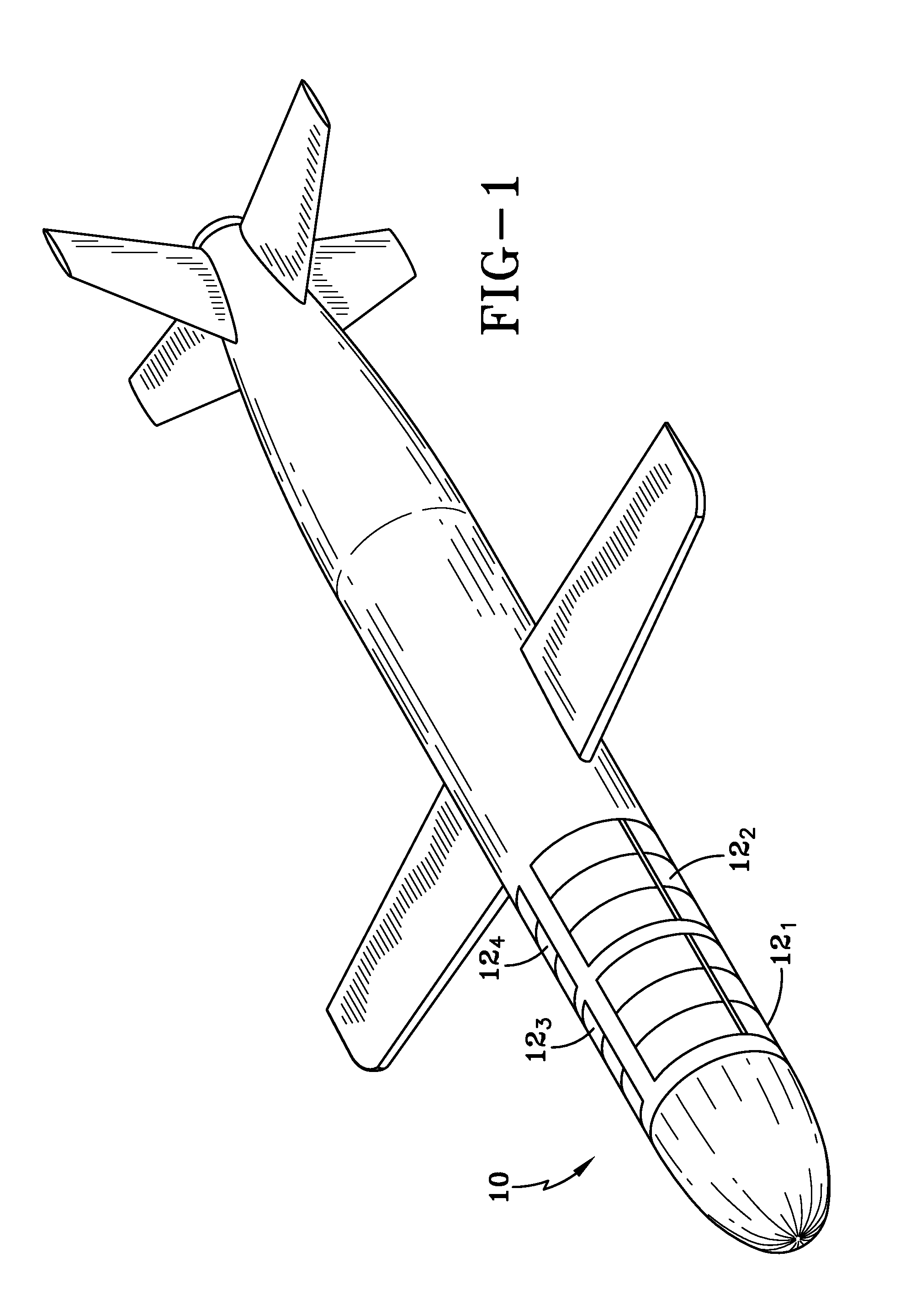
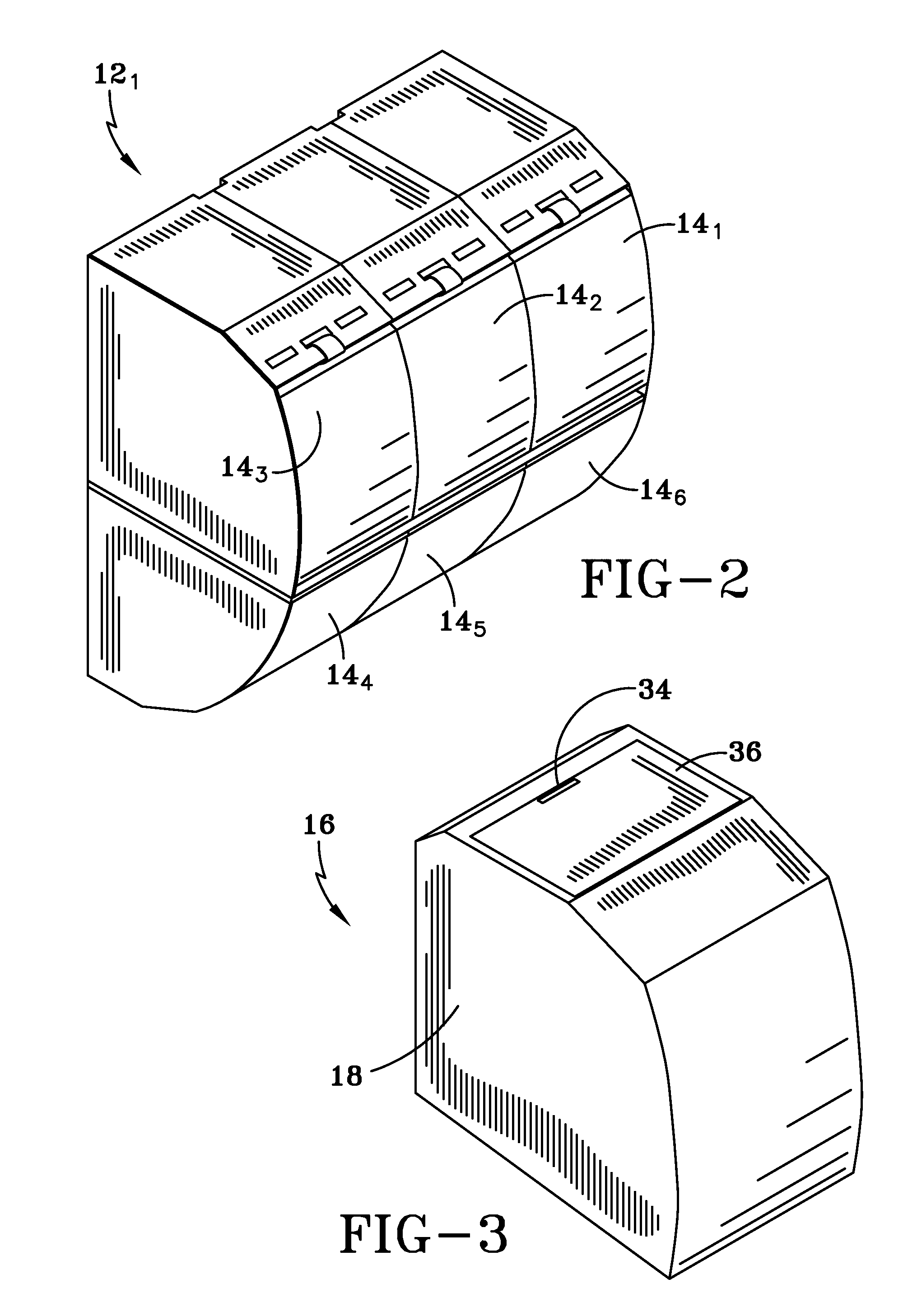
[0024]As discussed previously, deploying multiple Micro-Unmanned Aerial Vehicle (MUAV) has many benefits, but there are limitations concerning its range of operation. The present invention eliminates the range limitation by adapting a system for dispensing multiple short range vehicles, into a known submunition deployment system. The known submunition deployment system utilizes a cruise missile, such as a Tomahawk variant UGM 109D. This type of missile can be launched from submarine, surface or airborne locations. The present invention allows the MUAV to be insertable into and ejected from enclosed spaces of the missile both in a close sliding fit. More particularly, the present invention eliminates the problem of limited range by employing a cruise missile to dispense multiple MUAVs. The operation of the present invention may be better understood by first referring to FIG. 1.

[0025]FIG. 1 generally illustrates a cruise missile 10 that has payload bays, such as the known Tomahawk var...


PUM


Abstract

A micro-unmanned aerial vehicle deployment system is provided for a cruise missile having submunition compartments. The system includes a vehicle launch module releasable from the cruise missile submunition compartment. The vehicle launch system has a control circuit and at least one micro-unmanned aerial vehicle contained therein. Structure is provided in the launch module for deploying the micro-unmanned aerial vehicle. A separable tether can be joined between the cruise missile and the vehicle launch module that separates when subjected to tension after deployment of the vehicle launch module.

Description

STATEMENT OF GOVERNMENT INTEREST[0001]The invention described herein may be manufactured and used by or for the Government of the United States of America for governmental purposes without the payment of any royalties thereon or therefor.CROSS REFERENCE TO OTHER PATENT APPLICATIONS[0002]None.BACKGROUND OF THE INVENTION[0003](1) Field of the Invention[0004]The present invention relates to a device for deployment from a cruise missile and more particularly for submunition that is capable of deploying small unmanned aerial vehicles.[0005](2) Description of the Prior Art[0006]Tomahawk cruise missile variant UGM 109D is designed to deliver four payload modules of six small submunitions each to multiple targets. Submunitions are positioned in a submunition compartment with a close sliding fit and are retained in the compartment by a submunition latch. The submunition is deployed by a charge positioned in the submunition compartment which moves the submunition into the slipstream around th...

Claims


Application Information

Patent Timeline
Patent Type & Authority Patents(United States)
IPC IPC(8): B64C13/20
CPCF42B15/10B64C2201/206B64C2201/082B64C2201/121B64C2201/127F42B12/60B64C39/028B64C2201/128F42B15/00B64C13/20B64U70/20B64U2101/60B64U80/82
Inventor CARREIRO, PAUL, J.
Owner THE UNITED STATES OF AMERICA AS REPRESENTED BY THE SECRETARY OF THE NAVY
Learn More