

Centrifugal compressor
a centrifugal compressor and compressor technology, applied in the direction of machines/engines, liquid fuel engines, combustion air/fuel air treatment, etc., can solve the problems of narrow flow-rate range between the surge flow rate and the choke flow rate where stable operation is possible, inefficient operation of compressors, and inability to operate compressors. to achieve the effect of improving the surge margin, reducing the choke flow, and increasing the operation range of compressors
- Summary
- Abstract
- Description
- Claims
- Application Information
AI Technical Summary
Benefits of technology
Problems solved by technology
Method used
Image

Examples
first embodiment
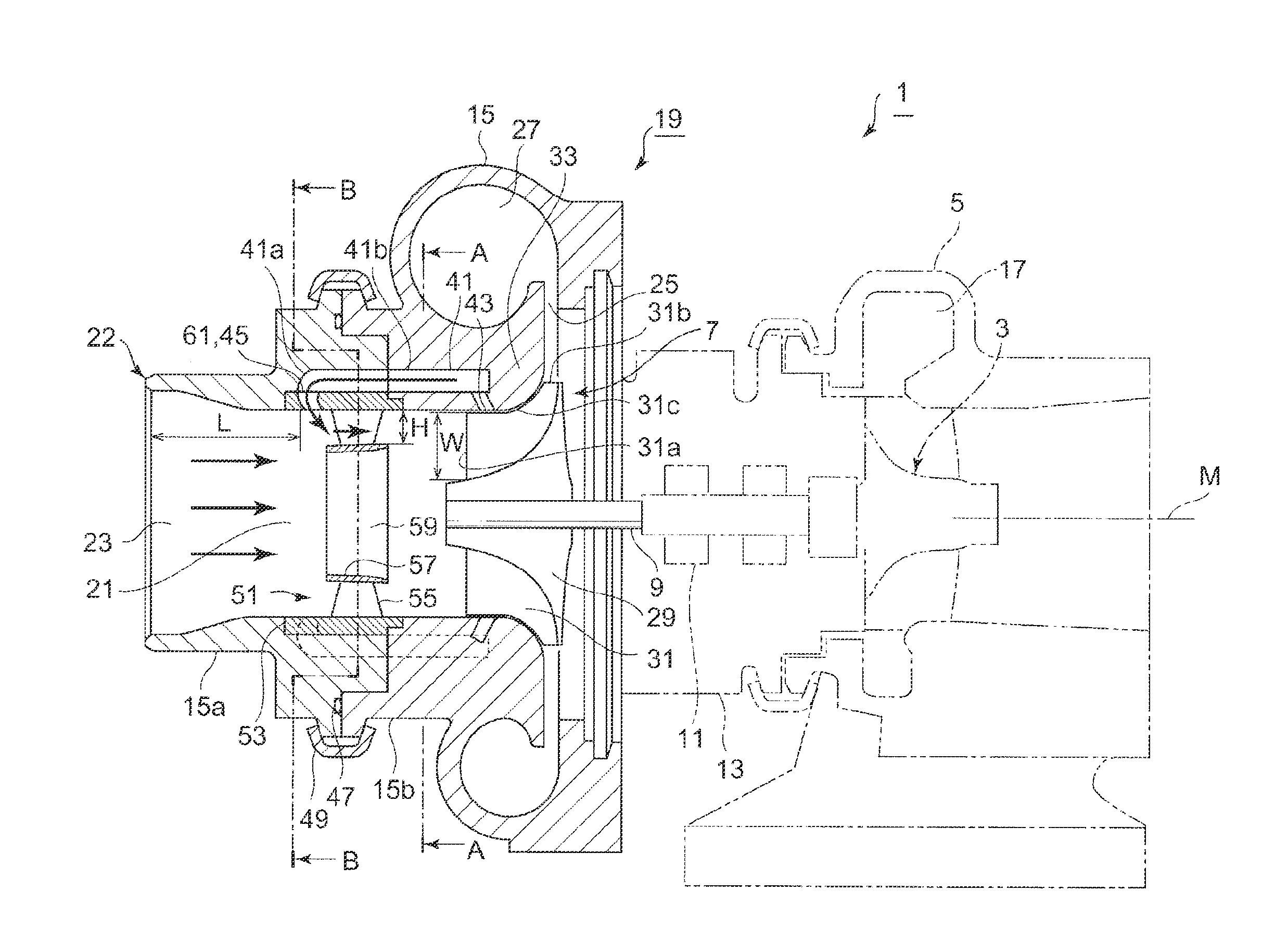
[0069]FIG. 1 is a partial cross-sectional view of an exhaust turbocharger 1 of an internal combustion engine in the direction of the rotational axis. The exhaust turbocharger 1 includes a turbine housing 5, a bearing housing 13, and a compressor housing 15 coupled together. The turbine housing 5 accommodates a turbine rotor 3 which is driven by exhaust gas of the internal combustion engine. The bearing housing 13 supports a rotational shaft 9 which transmits a rotational force of the turbine rotor 3 to an impeller wheel 7 to be freely rotatable via a bearing 11. The compressor housing 15 accommodates the impeller wheel 7 which draws in and compresses air as intake gas.
[0070]A scroll channel 17 of a spiral shape is formed on the outer circumferential part of the turbine housing 5 so as to surround the outer circumference of the turbine rotor 3, so that exhaust gas from the internal combustion engine flows toward the axial center from the outer circumferential side and exits in the ax...
second embodiment
[0120]Next, in reference to FIGS. 5 and 6, the second embodiment will be described.
[0121]The recirculation flow path 70 of the second embodiment is different from the first embodiment in that the recirculation flow path 70 includes a cylindrical slit-like void 71 instead of the plurality of circulation voids 41a formed in the upstream housing 15a. Other configurations are the same as those in the first embodiment.
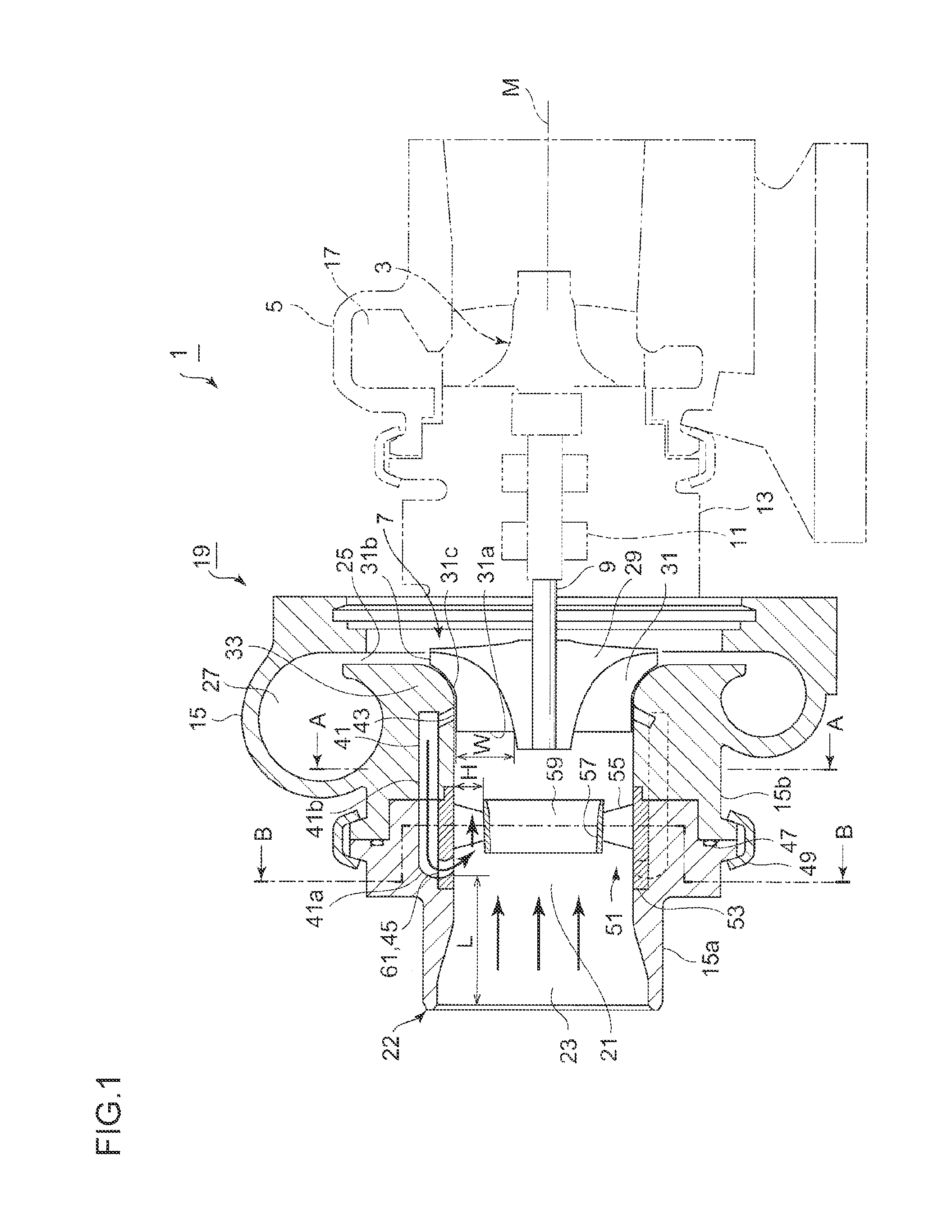
[0122]As illustrated in FIGS. 5 and 6, a single slit-like void 71 is formed by fitting the outer cylindrical member 53 of the swirl generating unit 51 to the inner circumferential wall of the upstream housing 15a so as to maintain a gap, in the radial direction, that has the substantially same length as the length of the shorter diameter (see FIG. 2) of the ellipse shape of the circulation voids 41b formed in the downstream housing 15b. The slit-like void 71 is formed by the outer circumferential surface of the outer cylindrical member 53 and the inner circumferential wall ...
third embodiment
[0126]Next, in reference to FIG. 7, the third embodiment will be described.
[0127]The third embodiment is different from the second embodiment in that the inner circumferential wall of the outer cylindrical member 53 of the swirl-flow generating unit 51 does not have a cylindrical shape but is curved in the direction of the rotational axis line M. Other configurations are the same as those in the second embodiment.
[0128]An outer cylindrical member 95 of a swirl-flow generating unit 93 is fitted to the inner circumferential wall of an upstream housing 91 so as to have a gap, in the radial direction, of the same length as the length of the shorter diameter (see FIG. 2) of the ellipse shapes of the plurality of circulation voids 41b formed in the downstream housing 15b.
[0129]Accordingly, a single slit-like void 97 of a substantially cylindrical shape is formed by the outer circumferential surface of the outer cylindrical member 95 and the inner circumferential wall of the upstream hous...
PUM
 Abstract
Description
Claims
Application Information