centrifugal compressor

A technology of centrifugal compressor and centrifugal impeller, which is applied in the direction of mechanical equipment, machine/engine, liquid fuel engine, etc., and can solve the problems of low surge margin of auxiliary power unit, constant efficiency of wedge-shaped diffuser, and decreased efficiency. Achieve the effects of reducing the loss of the diffuser, improving the surge margin and expanding the working range

Active Publication Date: 2018-12-07
CHINA AVIATION POWER MACHINE INST
View PDF8 Cites 0 Cited by
  • Summary
  • Abstract
  • Description
  • Claims
  • Application Information

AI Technical Summary

Problems solved by technology

[0005] The invention provides a centrifugal compressor to solve the technical problem of low surge margin of an auxiliary power unit while maintaining the same efficiency of the wedge diffuser or a small decrease in efficiency

Method used


Image

  • centrifugal compressor
  • centrifugal compressor
  • centrifugal compressor

Examples


Embodiment Construction

[0027] It should be noted that, in the case of no conflict, the embodiments in the present application and the features in the embodiments can be combined with each other. The present invention will be described in detail below with reference to the accompanying drawings and examples.

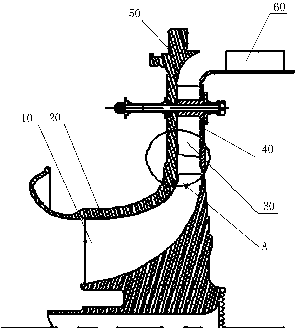
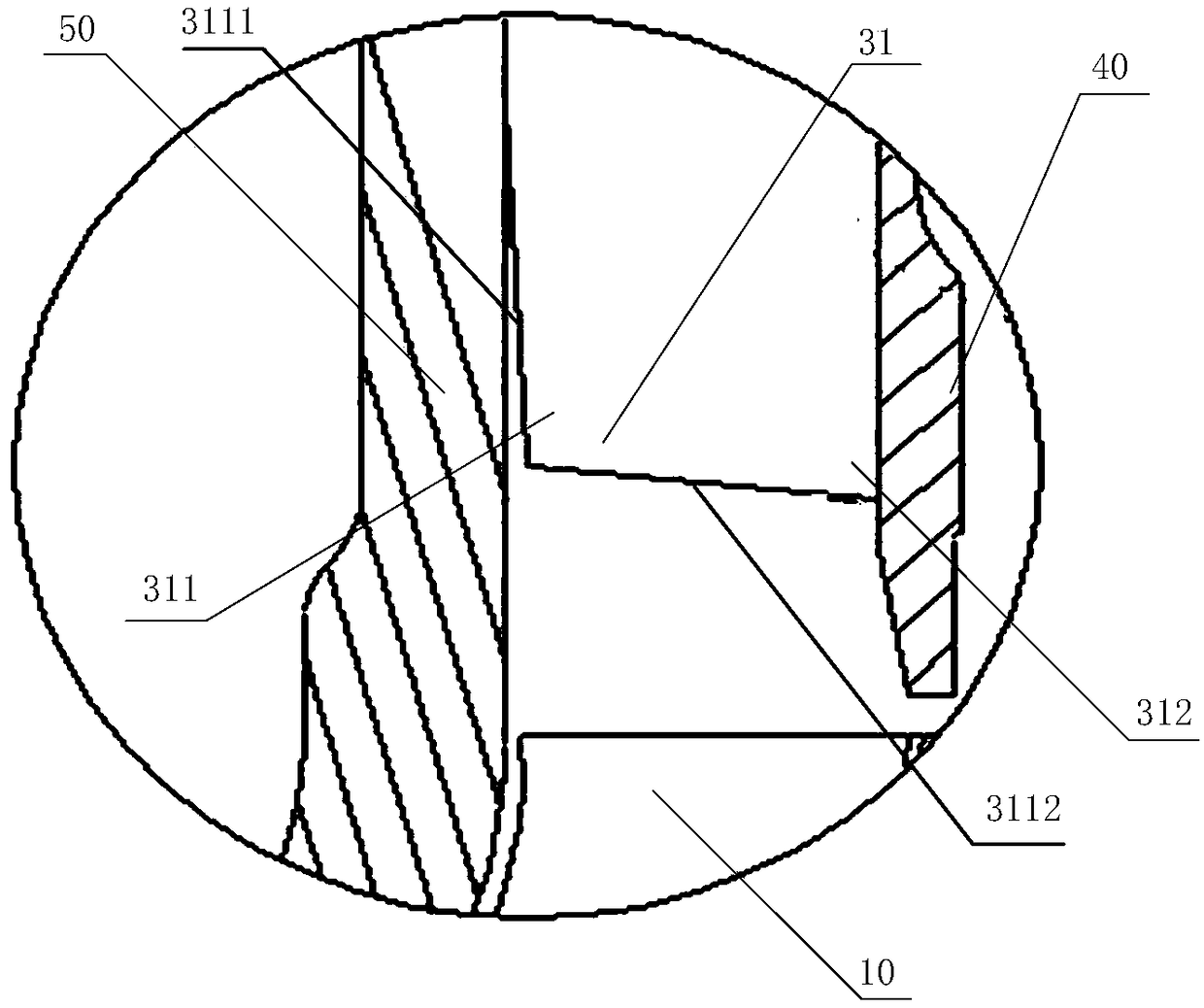
[0028] refer to figure 1 and figure 2 , a preferred embodiment of the present invention provides a centrifugal compressor, including a centrifugal impeller 10 for converting mechanical energy into kinetic energy of gas; surrounding the centrifugal impeller 10, and an air-inducing case 20 forming a first air flow passage with the centrifugal impeller 10 ; Located at the outlet of the first air flow passage, used to convert the kinetic energy of the gas converted by the centrifugal impeller 10 into a radial diffuser 30 of pressure energy; connected with the radial diffuser 30, used for positioning the radial diffuser 30 inner casing 40 of the diffuser; connected with the bleed air casing 20, u...


PUM


Abstract

The invention discloses a centrifugal compressor. The centrifugal compressor comprises a centrifugal impeller, an air bleeding receiver, a radial diffuser, a diffuser inner receiver and a diffuser outer receiver, wherein the centrifugal impeller is used for converting mechanical energy into gas kinetic energy; the air bleeding receiver is arranged around the centrifugal impeller and forms a first airflow passage together with the centrifugal impeller; the radial diffuser is positioned at an outlet of the first airflow passage and is used for converting the gas kinetic energy converted by the centrifugal impeller into pressure energy; the diffuser inner receiver is connected with the radial diffuser and is used for positioning the radial diffuser; the diffuser outer receiver is connected with the air bleeding receiver and is used for covering the radial diffuser; the radial diffuser is in a wedge shape and comprises a leading edge, the leading edge is positioned on one end which is close to the centrifugal impeller, the leading edge comprises a tip and a root which integrally extends together with the tip, and the tip is provided with a sweepback surface which sweeps back relatively to the root. According to the centrifugal compressor provided by the invention, the shape of the leading edge of the diffuser is changed, so as to adapt to the outlet airflow of the centrifugal impeller, thereby effectively reducing the diffuser loss, extending the working range and increasing the surge margin.

Description

technical field [0001] The invention relates to the field of aerodynamic design of a centrifugal compressor, in particular to a centrifugal compressor. Background technique [0002] The auxiliary power unit (APU) of aviation gas turbine is a small turbine engine, which has been widely used in military and civilian aircraft. However, the auxiliary power unit mainly provides compressed air for the starting of the main engine and the environmental control system of the aircraft, and its working characteristics determine that the working range of the engine is relatively large, so that the surge margin required for the centrifugal impeller is large. When the auxiliary power unit bleeds air, no matter in the active starting mode or the environmental control bleed air mode, in order to meet the work requirements, the bleed air pressure is high, and the compressor operating point is close to the surge boundary; at the same time, due to the unpredictable change of the bleed air volu...

Claims


Application Information

Patent Timeline
Patent Type & Authority Patents(China)
IPC IPC(8): F04D29/28F04D29/44F04D29/68
CPCF04D29/284F04D29/441F04D29/681
Inventor 曹四熊良军何风云李家俊
Owner CHINA AVIATION POWER MACHINE INST
Why Eureka
Try Eureka