A design method of impeller

A design method and impeller technology, which are applied in mechanical equipment, components of pumping devices for elastic fluids, non-variable-capacity pumps, etc. problem, to achieve the effect of improved design efficiency, high flow efficiency, compact geometry

Active Publication Date: 2020-08-28
TIANJIN UNIV
View PDF6 Cites 0 Cited by
  • Summary
  • Abstract
  • Description
  • Claims
  • Application Information

AI Technical Summary

Problems solved by technology

[0003] Casey proposed a compact one-dimensional design method for the centrifugal impeller, which is only for the axial inlet condition, the enthalpy coefficient is given as a constant, and the design result does not include the geometric structure parameters of the centrifugal impeller outlet, which makes it impossible to predict Swirling inlet impeller design, the design efficiency of the impeller is low

Method used


Image

  • A design method of impeller
  • A design method of impeller
  • A design method of impeller

Examples


Embodiment

[0106] Example: The design process of a centrifugal impeller with a compact pre-swirl air intake in an industrial transonic structure is as follows:

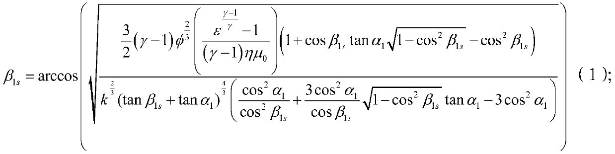
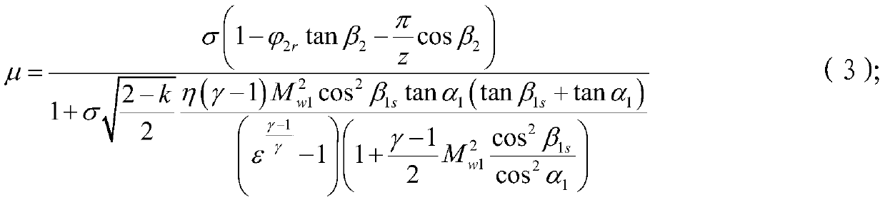
[0107]1) Given the design objectives of the centrifugal impeller: including isentropic efficiency η = 0.87, total pressure ratio ε = 6, flow coefficient φ = 0.12; given geometric constraints of the centrifugal impeller: including shape factor k = 0.85, radial airflow at the outlet of the centrifugal impeller Angle β 2 =38deg, centrifugal impeller outlet radial speed ratio The number of blades z=13, the specific enthalpy ratio σ=1.07, the centrifugal impeller inlet pre-rotation angle α 1 =30deg; given medium characteristic parameters: including gas constant R=287J / (kg k), adiabatic index γ=1.4;

[0108] 2) Set the initial enthalpy rise coefficient μ 0 =0.7;

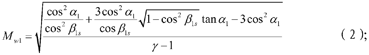
[0109] 3) Calculate the relative axial flow angle of the centrifugal impeller inlet cover, and the iterative result is β 1s =43deg;

[0110] 4) Calculate the relative...


PUM


Abstract

The invention discloses a design method of an impeller. The rapid and accurate impeller design method is provided, the aerodynamic performance and the design efficiency of the impeller are improved, and the method comprises the steps of giving the impeller dimensionless parameters; setting an initial enthalpy rise coefficient; calculating the optimal centrifugal impeller inlet impeller cover relative axial airflow angle; calculating the centrifugal impeller inlet impeller cover relative mach number; calculating the enthalpy rise coefficient; judging whether the relative error between the enthalpy rise coefficient and the initial enthalpy rise coefficient is smaller than 1% or not, if the relative error is larger than or equal to 1%, resetting the initial enthalpy rise coefficient; if the relative error is smaller than 1%, judging as iterative convergence and performing the next step; calculating the ratio of the centrifugal impeller inlet impeller cover diameter to the centrifugal impeller outlet diameter and the ratio of the centrifugal impeller outlet width to the centrifugal impeller outlet diameter; giving the centrifugal impeller dimensional parameters; and according to the calculation result and the given parameters, obtaining impeller design parameters. Through the method, the aerodynamic performance of the impeller can be improved, and the design period can be shortened.

Description

technical field [0001] The invention relates to the technical field of design of flow-passing parts of centrifugal and mixed-flow rotating machines, and more specifically relates to a design method of an impeller and its application. Background technique [0002] Centrifugal compressors are widely used in aero-engines, ground gas turbines, automobile and ship turbochargers, petrochemical compressors, and play an irreplaceable role in the fields of national defense and civil industry. Centrifugal impeller is the core component of centrifugal compressor, and its aerodynamic thermodynamic design is a key technology. At present, there are generally two types of centrifugal impeller design methods: the first type is positive proposition design, which obtains the initial design scheme through basic aerodynamic thermodynamic calculations, and then repeatedly modifies the geometric model according to the 3D numerical simulation results until the design requirements are met. The sec...

Claims


Application Information

Patent Timeline
Patent Type & Authority Patents(China)
IPC IPC(8): F04D29/28
CPCF04D29/284
Inventor 李孝检赵祎佳刘正先
Owner TIANJIN UNIV
Why Eureka
Try Eureka