
Scroll compressor and refrigerating apparatus

Inactive Publication Date: 2006-12-14
HITACHI JOHNSON CONTROLS AIR CONDITIONING INC
View PDF3 Cites 39 Cited by
  • Summary
  • Abstract
  • Description
  • Claims
  • Application Information

AI Technical Summary

Benefits of technology

[0013] It is an object of the invention to provide a scroll compressor, in which generation of wear and galling at tip ends of scrolls can be reduced and an operating range can be enlarged by enabling further decreasing a pressing force, with which one of scrolls is pressed against the other of the scrolls, and a refrigerating apparatus.
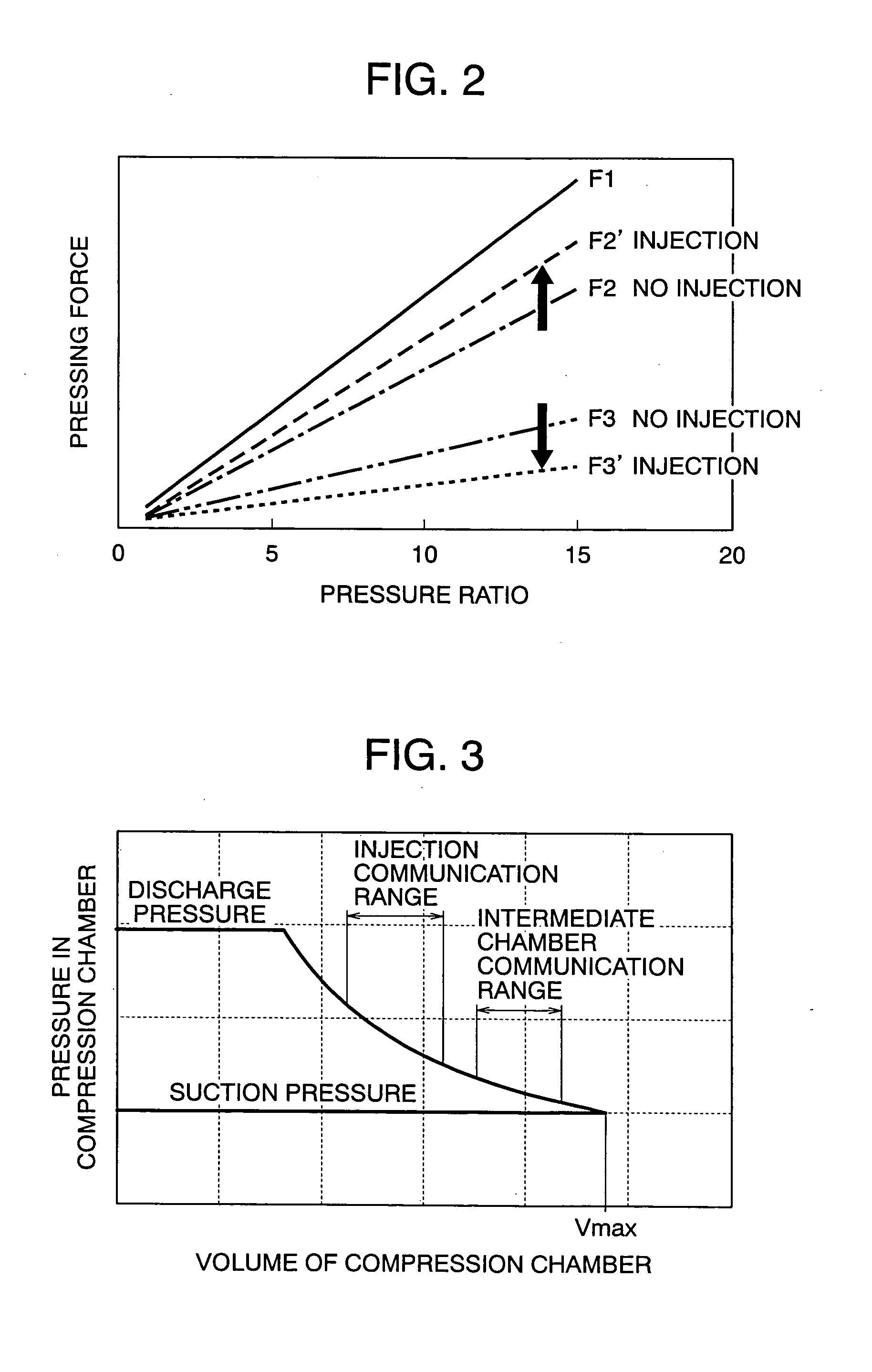
[0019] In this manner, by preventing the area, in which the intermediate pressure hole is opened to the compression chamber, and the area, in which the injection hole is opened to the compression chamber, from overlapping each other, arranging the injection hole in a position not communicated to the discharge space of the compressor, and arranging the intermediate pressure hole in a position not communicated to the suction space of the compressor, it is possible to reduce influences of the intermediate pressure on the back pressure chamber in case of gas injection and liquid injection, thus enabling stabilizing the behavior of the orbiting scroll.
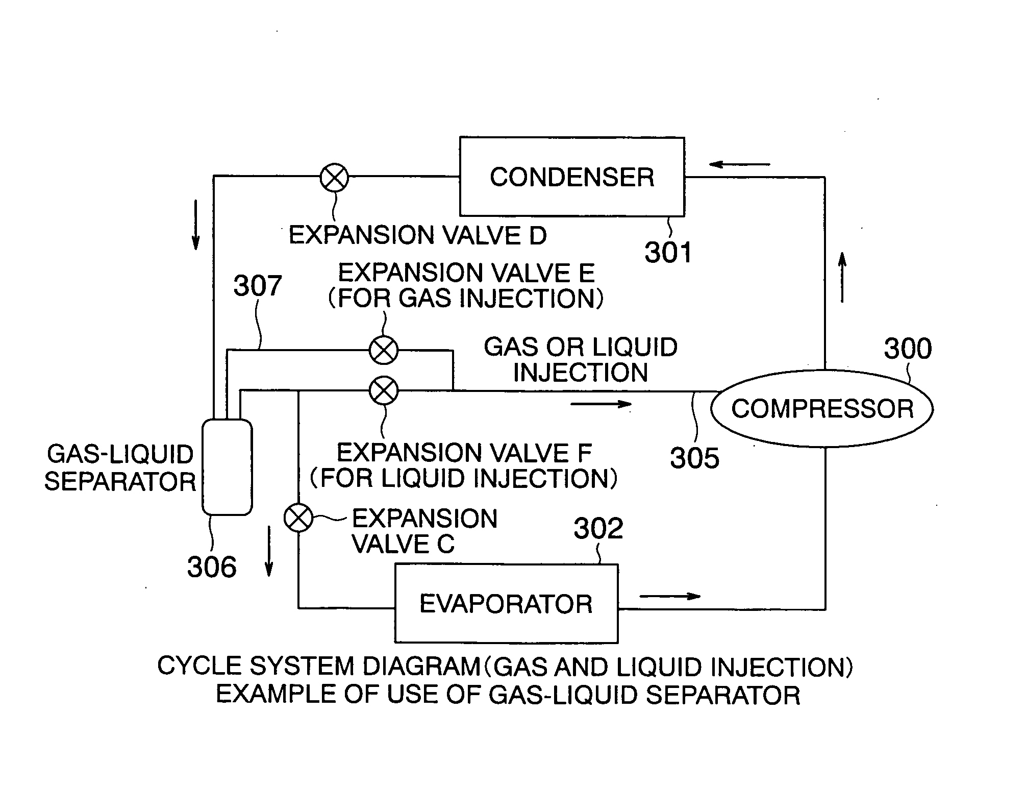
[0026] According to the invention, both of the gas refrigerant and the liquid refrigerant can be injected into the compression chamber from downstream of the condenser of the refrigerating cycle, and gas injection or liquid injection can be selected and carried out according to an operating condition of the compressor, so that it becomes possible to further decrease a pressing force, with which one of scrolls in a scroll compressor is pressed against the other of the scrolls, thus enabling reducing generation of wear and galling at tip ends of the scrolls and also enlarging an operating range.
[0027] Further, by arranging a position of the injection hole and a position of the intermediate pressure hole so as to prevent interference therebetween, it is possible to stabilize an orbiting scroll in behavior even under an operating condition, in which one of gas injection and liquid injection is used, whereby it is possible to obtain a compressor, which is improved in volume efficiency and small in vibration and noise.

Problems solved by technology

Therefore, there is caused a problem that, under the operating condition of a high pressure ratio, a contact surface pressure at tip ends of the scrolls becomes excessively large, and wear and galling are generated on the tip ends of the scrolls.

Method used


Image

  • Scroll compressor and refrigerating apparatus
  • Scroll compressor and refrigerating apparatus
  • Scroll compressor and refrigerating apparatus

Examples


Embodiment Construction

[0042] Embodiments of the invention will be described hereinafter.

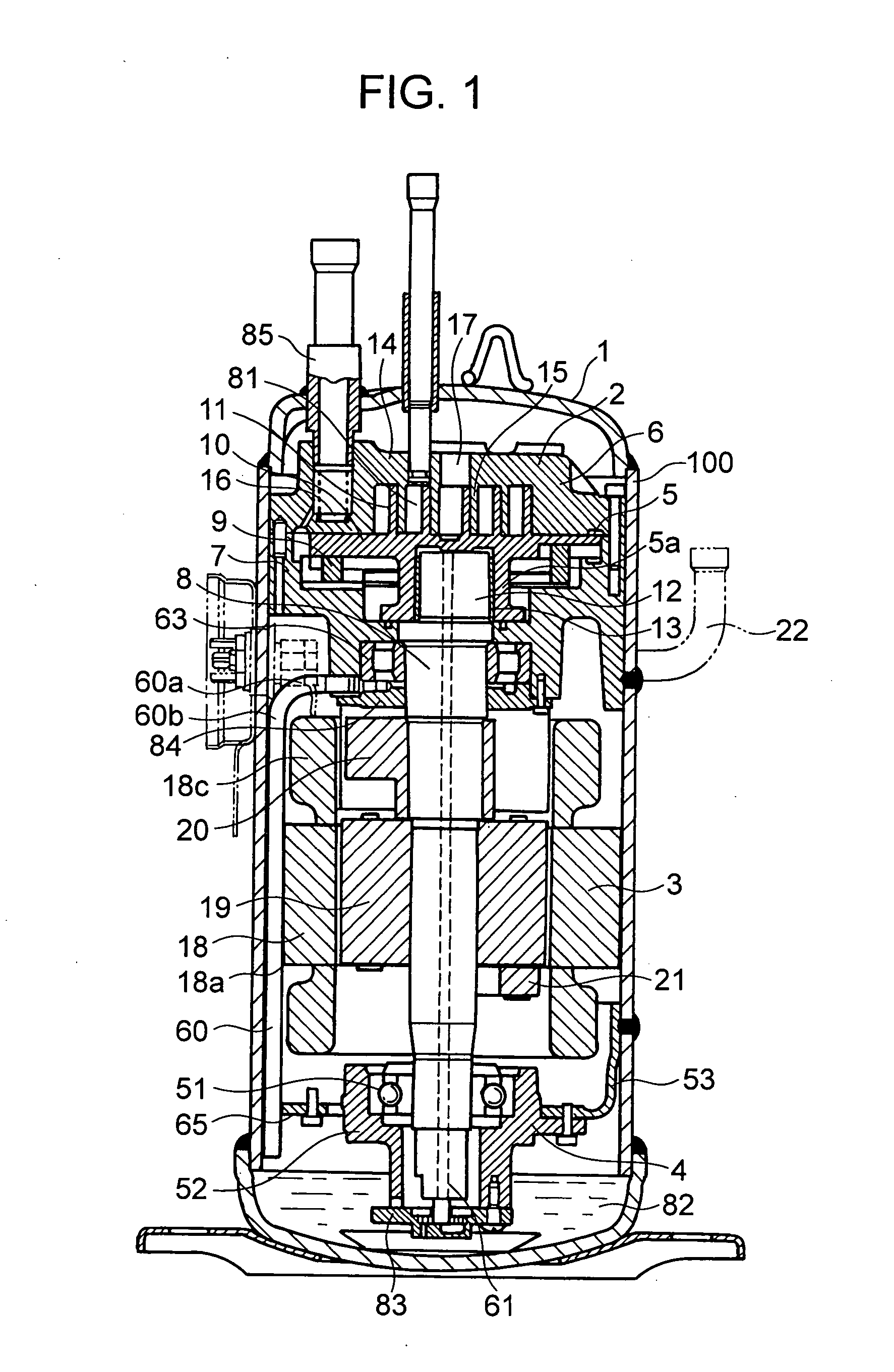
[0043] A scroll compressor according to the invention comprises a back pressure chamber provided on a back surface of an orbiting scroll or a fixed scroll and filled with gas refrigerant, and is constructed such that gas refrigerant pressure in the back pressure chamber presses one of the scrolls against the other of the scrolls. Further, the back pressure chamber is composed of a low pressure side space filled with suction gas or gas of intermediate pressure, and a high pressure side space filled with discharge gas, and one of the scrolls is pressed against the other of the scrolls by the summation of suction gas pressure or intermediate pressure and discharge gas pressure. Further, according to the invention, an injection hole is provided on the fixed scroll so that a gas refrigerant or a liquid refrigerant can be injected into a compression chamber, which is defined by the orbiting scroll and the fixed scroll.

[00...


PUM


Abstract

A scroll back pressure chamber in a scroll compressor is composed of a space 111 filled with suction pressure (or intermediate pressure) and a space filled with discharge pressure, and the summation of the suction pressure (or the intermediate pressure) and the discharge pressure presses one of scrolls against the other of the scrolls. An injection hole, through which refrigerant in gas state or refrigerant in liquid state is injected into a compression chamber of the scroll compressor, is provided on a fixed scroll, and the gas refrigerant injection or the liquid refrigerant injection is selected and carried out according to an operating pressure ratio.

Description

[0001] The present application claims priority from Japanese application JP 2005-170278 filed on Jun. 10, 2005, the content of which is hereby incorporated by reference into this application. BACKGROUND OF THE INVENTION [0002] The present invention relates to a scroll compressor comprising a scroll compression mechanism including a fixed scroll and an orbiting scroll and constructed such that a back pressure chamber filled with a gas refrigerant is provided on a back surface of an end plate at least one of the scrolls and a gas refrigerant pressure in the back pressure chamber presses one of the scrolls against the other of the scrolls, and a refrigerating apparatus. [0003] There is known a scroll compressor comprising a compression mechanism including a fixed scroll, an orbiting scroll, etc. and a drive unit that drives the compression mechanism, wherein the compression mechanism and the drive unit are received in a closed vessel, and such compressor is frequently used in a refrige...

Claims


Application Information

Patent Timeline
IPC IPC(8): F25B41/00F25B1/00
CPCF04C27/005F04C29/042F25B1/04F25B1/10F25B40/02F25B2700/21152F25B2400/13F25B2400/16F25B2500/19F25B2700/1931F25B2700/1933F25B2341/066F25B41/385F25B41/39F04C18/02F25B31/00
Inventor NAKAMURA, SATOSHIMATSUNAGA, MUTSUNORIHASEGAWA, SHUJITOJO, KENJI
Owner HITACHI JOHNSON CONTROLS AIR CONDITIONING INC
Learn More