Flow rate control device in a hydraulic excavator

a flow control and hydraulic excavating technology, applied in the direction of fluid couplings, servomotors, couplings, etc., can solve the problems of reducing the discharge flow rate, and affecting the operation of hydraulic excavators

Inactive Publication Date: 2001-03-20
KOBELCO CONSTR MASCH CO LTD
View PDF4 Cites 54 Cited by
  • Summary
  • Abstract
  • Description
  • Claims
  • Application Information

AI Technical Summary

Problems solved by technology

Generally, it is known that once the relief cut-off control is made, the operator of the hydraulic excavator feels a sense of incongruity or feels as if force were gone, as an

Method used


Image

  • Flow rate control device in a hydraulic excavator
  • Flow rate control device in a hydraulic excavator
  • Flow rate control device in a hydraulic excavator

Examples


fourth embodiments

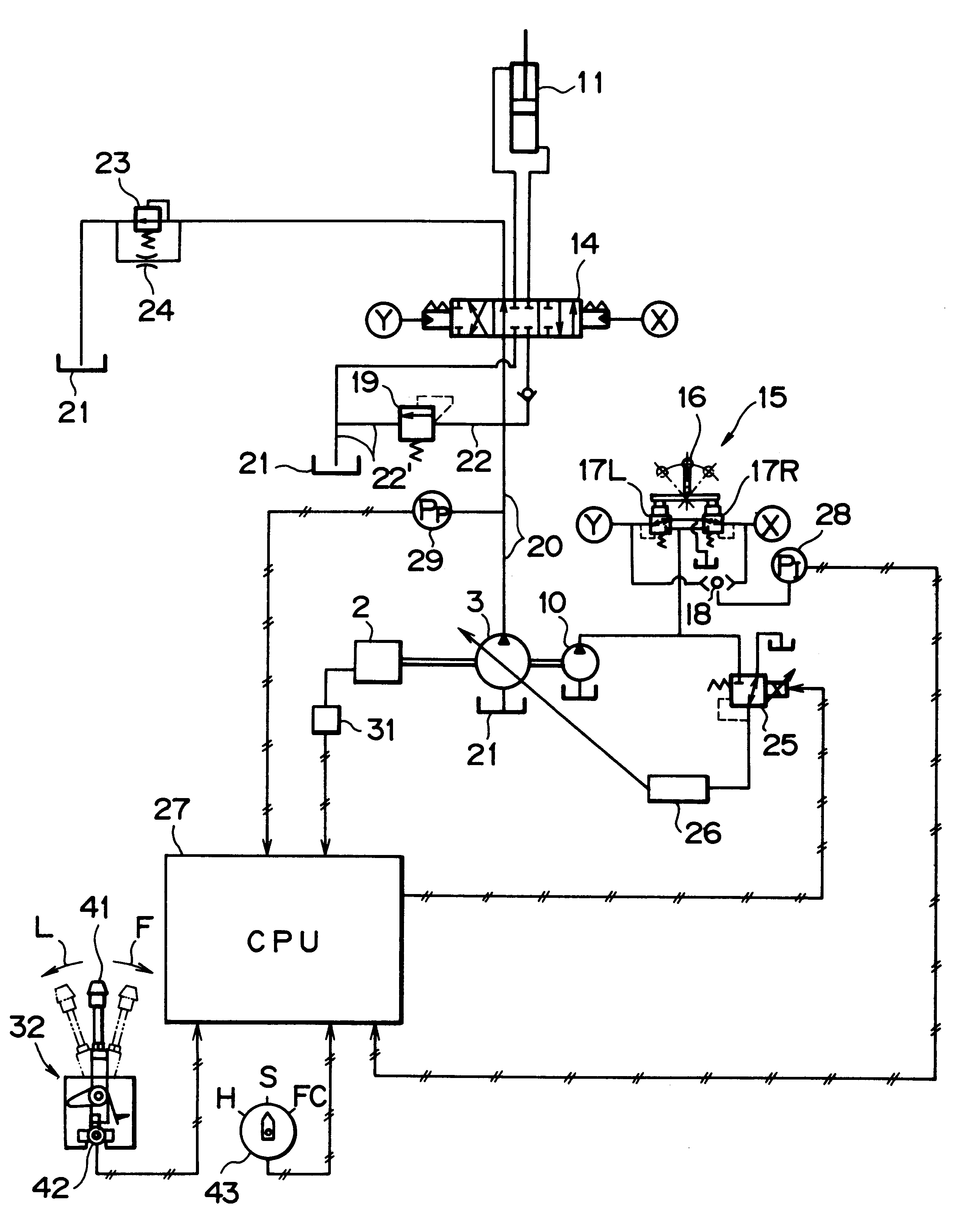
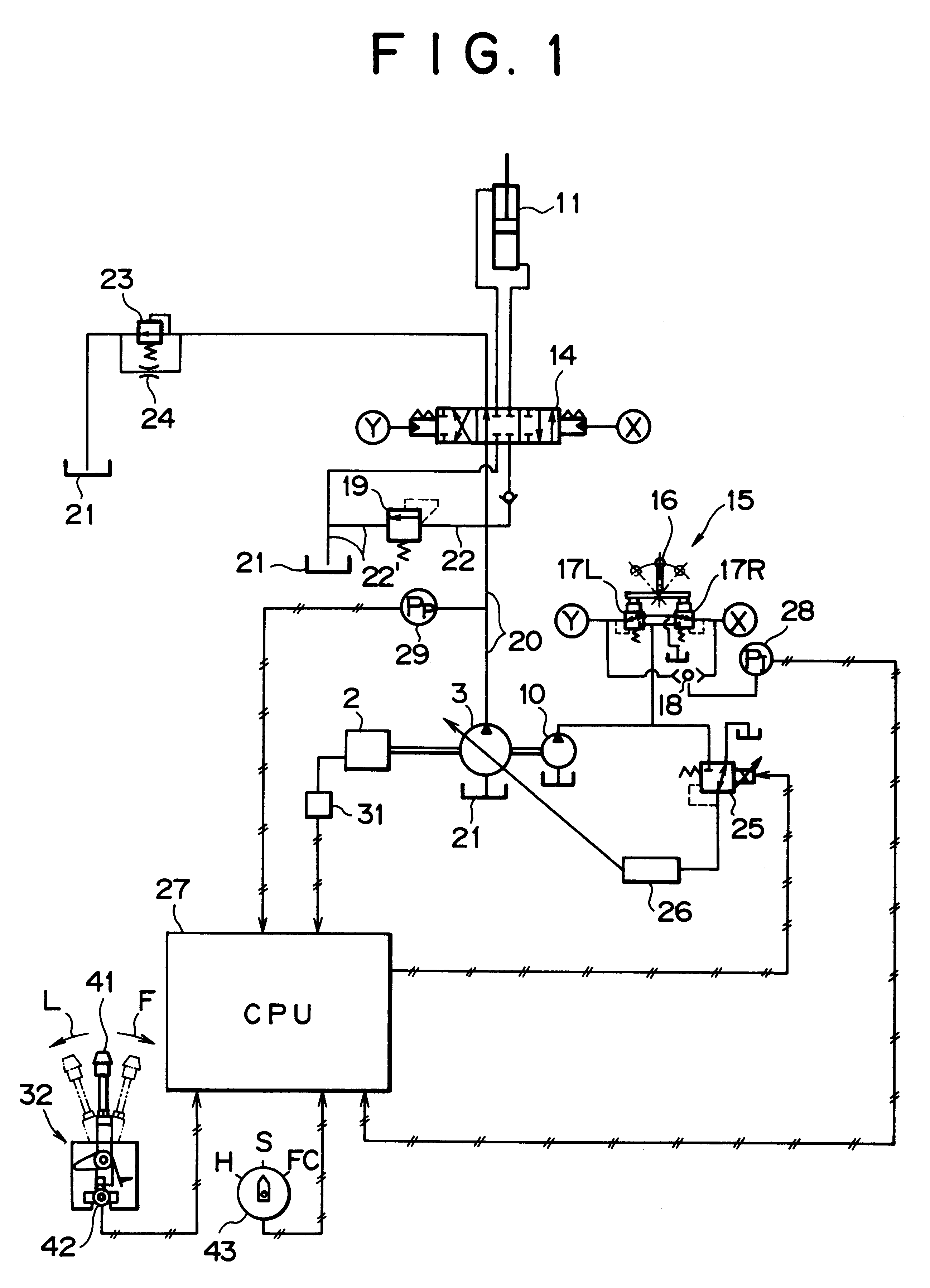
These first to fourth embodiments will now be described in detail with reference again to FIG. 1. Although FIG. 1 is described as if all of the above conditions 1 to 4 were taken into consideration (that is, as if the flow control device shown therein corresponded to the fourth embodiment), this is for the convenience of making reference to FIG. 1 with respect to all of the first to As will be seen from the following description, it suffices if only detection values and set values required in each of the embodiments are inputted to the controller 27.

first embodiment

Reference will first be made to the While the hydraulic excavator is in operation, the pump pressure sensor 29 detects the discharge pressure in the discharge line 20 of the discharge oil which is discharged from the hydraulic pump 3. Signals thus detected are inputted to the controller 27 at every generation. The pilot pressure sensor 28 detects a pilot pressure of the hydraulic remote control valve 15 and signals thus detected are inputted to the controller 27 at every generation. On the basis of these detected signal provided from the pilot pressure sensor 28 the controller 27 determines an operation quantity of the hydraulic remote control valve 15. In the case where a predetermined attachment other than an excavating bucket, say, a crusher, is attached to the hydraulic excavator, signals provided from an operating lever, an operating pedal, or an operating switch, (none of them are shown), for operating the attachment are inputted to the controller 27. On the basis of these si...

second embodiment

FIG. 4 is a flowchart showing a function related to relief cut-off control ON of the controller 27. The following description is now provided on the basis of the conditions set forth in the foregoing After updating of the relief cut-off pressure in the relief valve 19 (S1), if all of the following conditions are satisfied: the revolution of the engine 2 should be not lower than a predetermined number of revolutions (S2), the hydraulic actuator should be in a specific operational condition (S3), and the pump pressure should be not lower than the relief cut-off pressure (S4), and if these conditions are maintained for a predetermined period of time (S5, S6), Relief Cut-off Flag turns ON (S7) and a command value signal is outputted from the controller 27 to the electromagnetic proportional reducing valve 25 (S8). FIG. 5 is a flowchart showing command values of signals outputted to the electromagnetic proportional reducing valve 25 from the controller 27 which performs the relief cut-o...


PUM


Abstract

A flow rate control device in a hydraulic excavator, comprising a hydraulic pump which is driven rotatively by an engine, a hydraulic actuator which is driven by a hydraulic oil discharged from the hydraulic pump, a control valve which controls the supply of the hydraulic oil to the hydraulic actuator, an operating means which operates the control valve so as to change over the valve from one position to another, a relief valve disposed in a discharge oil path extending from the hydraulic pump to limit the maximum pressure in the discharge oil path, an operational condition detecting means for detecting an operational condition of the hydraulic actuator, a pump pressure detecting means for detecting the discharge pressure of the hydraulic oil discharged from the hydraulic pump, a flow rate adjusting means for adjusting the discharge flow rate of the hydraulic oil discharged from the hydraulic pump, and a control means to which are inputted detection signals from both the operational condition detecting means and the pump pressure detecting means. When a specific operational condition of the hydraulic actuator is detected and when the said discharge pressure is held at a predetermined relief cut-off pressure or higher for a predetermined period of time, the control means makes control so that the discharge flow rate of the hydraulic oil discharged from the hydraulic pump is decreased to a relief cut-off pressure by the flow rate adjusting means. According to this construction, the relief cut-off control can be made only where required for each of various works of different conditions which the hydraulic excavator performs, such as excavating work, crushing work and land readjusting work. That is, even when the discharge pressure is held at a predetermined relief cut-off pressure or higher for a predetermined period of time, the relief cut-off control is made if the hydraulic actuator is in the specific operational condition.

Description

1. Field of the InventionThe present invention relates to a flow rate control device for use in relief cut-off control in a hydraulic excavator.2. Description of the Related ArtIn a certain hydraulic excavator there is made a control called relief cut-off control in which the discharge flow rate from a pump is decreased when the pump pressure has reached a relief cut-off pressure. Once this relief cut-off control is made, for example when a rock or the like strikes against a bucket during excavating work of the hydraulic excavator and an overload acts on the excavator, it is not only possible to prevent the energy loss of hydraulic oil caused by relief operation but also possible to diminish the relief noise. Besides, there does not occur any shock during relief operation, so it becomes possible to effect smooth operation and it is also possible to improve the heat balance of hydraulic oil and devices.In the conventional hydraulic excavator, however, the relief cut-off control is ma...

Claims


Application Information

Patent Timeline
IPC IPC(8): E02F9/22F15B11/00F15B21/08F15B21/00F15B11/028
CPCE02F9/2235E02F9/2285E02F9/2296F15B11/028F15B21/087F15B2211/20515F15B2211/20538F15B2211/20553F15B2211/30505F15B2211/30525F15B2211/3116F15B2211/40507F15B2211/41554F15B2211/50518F15B2211/50536F15B2211/528F15B2211/55F15B2211/6309F15B2211/6316F15B2211/633F15B2211/6346F15B2211/6355F15B2211/6652F15B2211/7053
Inventor YAMASHITA, KOUJI
Owner KOBELCO CONSTR MASCH CO LTD
Why Eureka
Try Eureka