System and process for introducing a rigid lance into a concrete mixing truck using an articulated arm

a technology of concrete mixing truck and rigid lance, which is applied in the field of system and process for introducing rigid lance into concrete mixing truck using an articulated arm, can solve the problems of high labor intensity, high labor intensity, and high cost of concrete poured at high temperatures, and achieve the effect of reducing the chance of a destructive collision of rigid lan

Active Publication Date: 2014-04-29
AIR LIQUIDE IND US LP
View PDF9 Cites 20 Cited by
  • Summary
  • Abstract
  • Description
  • Claims
  • Application Information

AI Technical Summary

Benefits of technology

[0008]The present invention provides a system for injecting a cooling fluid into a concrete mixing container. The system includes a support structure and a lance device that is mounted, preferably movably, on to the support structure. The lance device used in the system comprises an articulated arm and a means that acts on the articulated arm to cause the movement of a rigid lance that is an integral part of the articulated arm. The means that acts on the articulated arm may be either a lone electric actuator or a lone electric motor. The means that acts on the articulated arm provides the ability to exactly position the rigid lance and reduce the chance of a destructive collision of the rigid lance with the concrete mixing container. The means acts on the articulated arm in such as manner as to allow for pivotal non-linear movement of the rigid lance relative to the support structure and concrete mixing container. This pivotal non-linear movement results from the pivotal movements of the various components of the articulated arm with regard to one another (movements that encompass the combined movement across the X and Z axis at the same time). More specifically, the extension or retraction of the actuator or rotational control of the motor allows for control of the angle of the rigid lance while at the same time controlling the insertion and retraction movement of the rigid lance into the concrete mixing container. The present invention further relates to a process for the injection of a cooling fluid into a concrete mixing container utilizing the system of the present invention.

Problems solved by technology

Concrete that is poured at high temperatures will often not meet the minimum strength requirements, especially in warm weather climates.
The first approach was found to present problems in terms of cost, timeliness, labor intensity, additional equipment, safety issue and final product issues.
The second approach was found to present problems because of potential damage to the truck mixer drum.
The manually intensive systems are typically lower in cost, but are less productive and less safe.
The highly automated systems are more productive and safer to operate, but they have a higher cost to manufacture and maintain.
While multiple prior art systems have sought to overcome the issues associated with these systems by providing relatively inexpensive systems that adjust to accommodate the relative position and particular specifications of a given container without so much manual intervention, there are still problems with these systems.
The cylinder can be controlled to either fully extend or to either fully retract, but are not capable of partially extending / retracting.
If the lance or truck is positioned in a way so as to introduce a collision hazard, the operator often does not have enough time to react to prevent a collision.
This collision often results in lance or mixer damage and often causes the lance to detach from the pneumatic cylinder.
When the lance is detached, it must be manually returned to its proper position which results in significant down time.
The practice of returning the lance to its original position is complicated since it often requires additional manpower and equipment to complete the task.
The more complex a device is, however, the more expensive it is to fabricate and maintain.
In addition, complexity negatively affects fabrication, installation, and removal lead times, which adds to the cost of operation.
It is the further objection to provide a system that eliminates damage to the lance device, particularly the rigid lance, in situations where the concrete mixer truck is repositioned before completion of the injection of the cooling fluid.

Method used


Image

  • System and process for introducing a rigid lance into a concrete mixing truck using an articulated arm
  • System and process for introducing a rigid lance into a concrete mixing truck using an articulated arm
  • System and process for introducing a rigid lance into a concrete mixing truck using an articulated arm

Examples


first embodiment

[0032]The First Embodiment involves the pivotal connection of the vertical support member directly to the first end of the lower guide arm and the use of an actuator as the means to move the articulating arm. In this particular embodiment, a mounting bracket for the lance device is preferably located on the lower part of the back or external surface of the vertical support member. The vertical support member may form a portion of the mounting bracket, in which case a mounting bracket member will be bolted to the lower portion of the vertical support member to allow for an open space between the mounting bracket member and the vertical support member in which the cross member beam will be positioned. As described hereinafter, a variety of additional components such as mounting bracket submembers, bearings and / or clamps can be disposed within the space to secure the cross member beam securely between the vertical support member and the mounting bracket member. Alternatively, the mount...

second embodiment

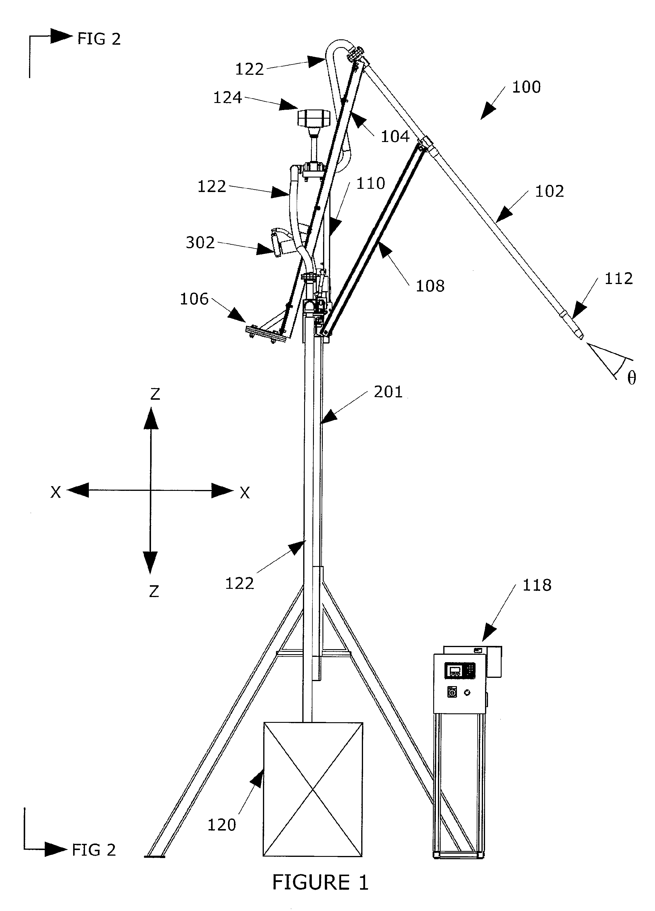
[0038]In an alternative and more preferred embodiment, one end of the actuator is attached to the back or external surface of the vertical support member between the lower end of the vertical support member and the fulcrum. In this same embodiment, the opposing end of the actuator is attached to the upper lifting arm at a point between the first end of the upper lifting arm and the fulcrum. These connections are also such that when the shaft of the actuator is extended or retracted, actuation of the upper lifting arm causes the pivotal movements of the remaining components of the articulated arm in a non-linear motion which allows for the resulting control of the angle of the rigid lance while at the same time allowing for the insertion and retraction movement of the rigid lance into the concrete mixing container for fluid injection. In this particular embodiment (with the actuator being positioned in the back or external surface of the vertical support member), the rigid lance is w...

fourth embodiment

[0063]In the particular embodiment demonstrated by FIG. 3, the mounting bracket (314) is located on the external surface of the vertical support member (110). A further modification to this involves placing the mounting bracket (314) between the breakaway bracket (304) and the vertical support member (110) as represented by the Fourth Embodiment discussed hereinbefore and shown in FIG. 7. In this particular embodiment, the mounting bracket (314) is rigidly attached on one side to the vertical support member (110) and pivotally attached on the opposing side to the breakaway bracket (304). The breakaway bracket (304) is further pivotally attached at a different point to the lower guide arm (108).

[0064]In FIG. 3a, the mounting bracket (314) is positioned between the lower end (110B) of the vertical support member (110) and the first end (108A) of the lower guide arm (108). The mounting bracket is rigidly attached to the vertical support member (110) and pivotally connected along the op...


PUM

PropertyMeasurementUnit
angleaaaaaaaaaa
length of travelaaaaaaaaaa
angleaaaaaaaaaa

Abstract

A present invention provides for a system (100) for injecting cooling fluid into a concrete mixing container (502), the system (100) comprising a support structure (116) having a leg assembly with two or more supporting legs (201) and a cross member beam (200) supported between said two or more legs (201), the two or more legs (201) and the cross member beam (200) being positioned with respect to one another in such a manner as to define a passageway (210) of sufficient height (H) and width (W) between the two or more legs (201) and beneath the cross member beam (200) to allow passage of a concrete mixer truck (504) through the passageway (210) and a lance device (190) positioned on the cross member beam (200) of the support structure (116), the lance device (190) comprising an articulated arm that includes a rigid lance (102) which allows for the flow of a cooling fluid there through; and a means for acting on the articulated arm to cause pivotal movement of the articulated arm in a non-linear motion thereby controlling the angle of the rigid lance (102) while at the same time controlling the insertion and retraction movement of the rigid lance (102) into the concrete mixing container (502) for fluid injection of the cooling fluid into the concrete mixing container (502). The present invention further comprises a process for injecting cooling fluid into a concrete mixing container (502).

Description

FIELD OF THE INVENTION[0001]The present invention relates to an apparatus and process for injecting a cooling fluid into a concrete mixing container utilizing a system which includes a lance device having an articulated arm.BACKGROUND[0002]The state of the art for cryogenic concrete cooling is well documented in WO 2006 / 100550 as filed by Air Liquide. As noted in WO 2006 / 100550, when preparing concrete it is often necessary to cool the concrete mix since the structural integrity of the resulting concrete is dependent upon the temperature at which the concrete is set. Typically, the cooler the concrete when poured, the stronger it will be once it is set. Concrete that is poured at high temperatures will often not meet the minimum strength requirements, especially in warm weather climates.[0003]In the past, this issue was addressed in a number of ways including 1) cooling the water used in mixing the concrete using a refrigeration unit, ice, or a cryogenic liquid which was mixed with ...

Claims


Application Information

Patent Timeline
Patent Type & Authority Patents(United States)
IPC IPC(8): B28C5/06
CPCB28C5/468B28C7/126C04B40/0683
Inventor BILGER, STEPHEN
Owner AIR LIQUIDE IND US LP
Why Eureka
Try Eureka