Light modulators and optical apparatuses including the same

a technology applied in the field of light modulators and optical apparatuses, can solve problems such as low operation speed

Active Publication Date: 2014-04-29
SAMSUNG ELECTRONICS CO LTD
View PDF15 Cites 15 Cited by
  • Summary
  • Abstract
  • Description
  • Claims
  • Application Information

AI Technical Summary

Problems solved by technology

These light modulators typically have a long response time of several microseconds (μs) due to their driving methods (mechanisms), and thus, they have a low operation speed.

Method used


Image

  • Light modulators and optical apparatuses including the same
  • Light modulators and optical apparatuses including the same
  • Light modulators and optical apparatuses including the same

Examples


Embodiment Construction

[0059]The following description is provided to assist the reader in gaining a comprehensive understanding of the methods, apparatuses, and / or systems described herein. Accordingly, various changes, modifications, and equivalents of the methods, apparatuses, and / or systems described herein may be suggested to those of ordinary skill in the art. Also, descriptions of well-known functions and constructions may be omitted for increased clarity and conciseness.

[0060]A light modulator as described herein may be used in various optical apparatuses such as a display device, a camera, a television, a projector, a display of a terminal, and the like. For example, the light modulator may be used as a color pixel for modulating colors of a display device.

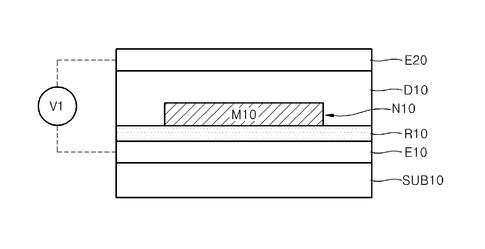
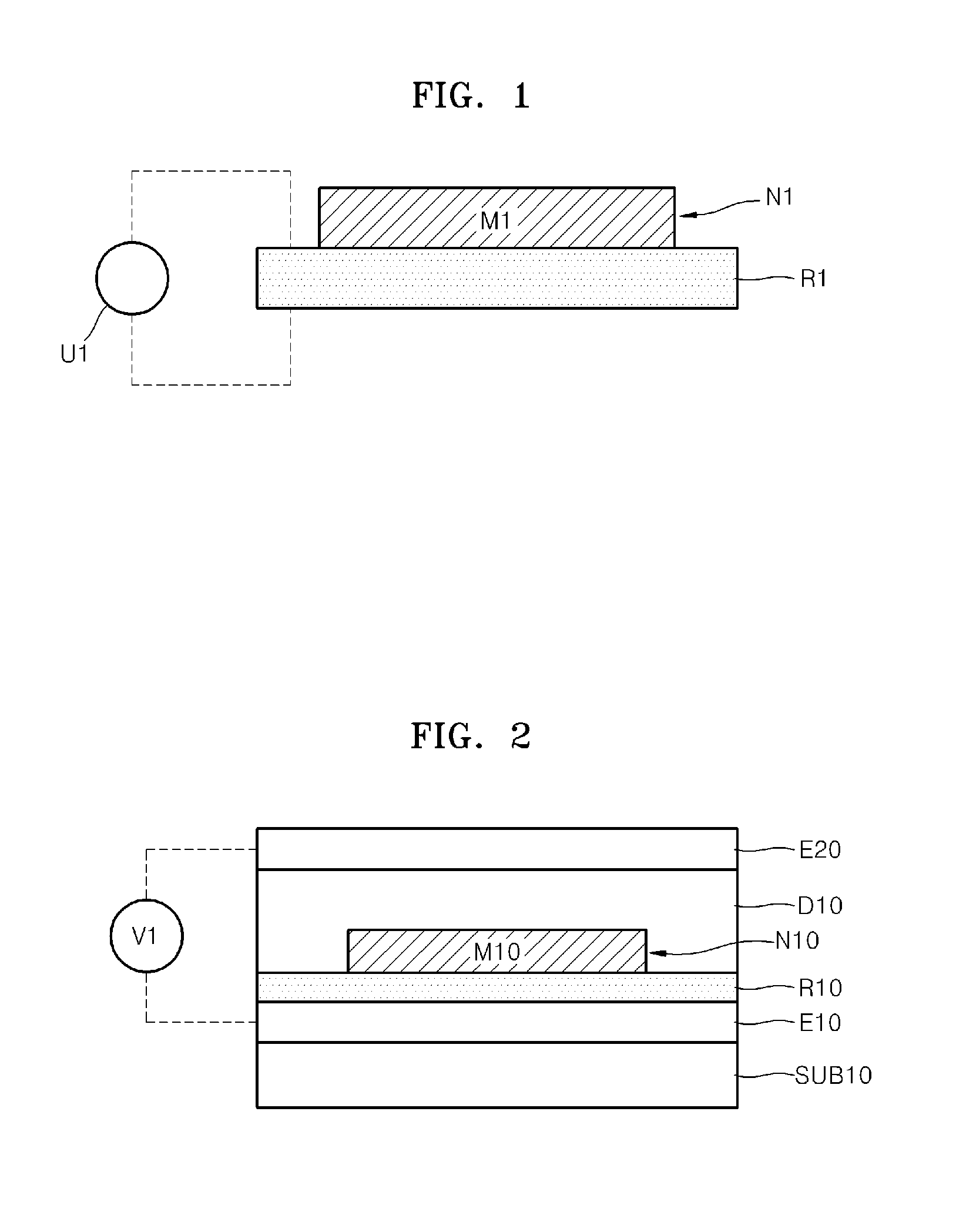
[0061]FIG. 1 illustrates an example of a light modulator.

[0062]Referring to FIG. 1, the light modulator includes a plasmonic nano-antenna N1 and a refractive index change layer R1 disposed adjacent to the plasmonic nano-antenna N1. The plasmoni...


PUM

PropertyMeasurementUnit
refractive indexaaaaaaaaaa
thicknessaaaaaaaaaa

Abstract

Provided are examples of light modulators and optical apparatuses that may include the light modulators. A light modulator may include a plasmonic nano-antenna and an element for changing plasmon resonance characteristics of the plasmonic nano-antenna. The plasmon resonance characteristics of the plasmonic nano-antenna may be changed due to a change in refractive index of the element, and thus light may be modulated.

Description

CROSS-REFERENCE TO RELATED APPLICATION(S)[0001]This application claims the benefit under 35 U.S.C. §119(a) of Korean Patent Application No. 10-2010-0139356, filed on Dec. 30, 2010, in the Korean Intellectual Property Office, the entire disclosure of which is incorporated herein by reference for all purposes.BACKGROUND[0002]1. Field[0003]The following description relates to light modulators and optical apparatuses including the same.[0004]2. Description of the Related Art[0005]General light modulators control the flow or characteristics of light such as the direction, a degree of transmission or reflection, and the like. Light modulators typically use a mechanical motion of a light blocking or changing element, liquid crystals, a structure of a microelectromechanical system (MEMS), and the like, to control light. These light modulators typically have a long response time of several microseconds (μs) due to their driving methods (mechanisms), and thus, they have a low operation speed....

Claims


Application Information

Patent Timeline
Patent Type & Authority Patents(United States)
IPC IPC(8): G02F1/01G02F1/19
CPCG02F1/19G02B5/008B82Y20/00G02F1/01G02F2203/10G02F1/0102G02B26/02
Inventor HAN, SEUNG-HOONPARK, YONG-HWASHIN, CHANG-GYUNLEE, HONG-SEOK
Owner SAMSUNG ELECTRONICS CO LTD
Why Eureka
Try Eureka