
Polarized film apparatus with bands of alternating orientation

a technology of polarized films and alternating orientation, applied in the field of polarized films, can solve the problems of prohibitive residential applications, film permanently affixed to the window does not offer any flexibility in the amount of light transmitted or privacy, and the cost of such systems is prohibitive, so as to achieve the effect of less cost and easy installation

Inactive Publication Date: 2014-04-29
INICIA IP HLDG
View PDF14 Cites 1 Cited by
  • Summary
  • Abstract
  • Description
  • Claims
  • Application Information

AI Technical Summary

Benefits of technology

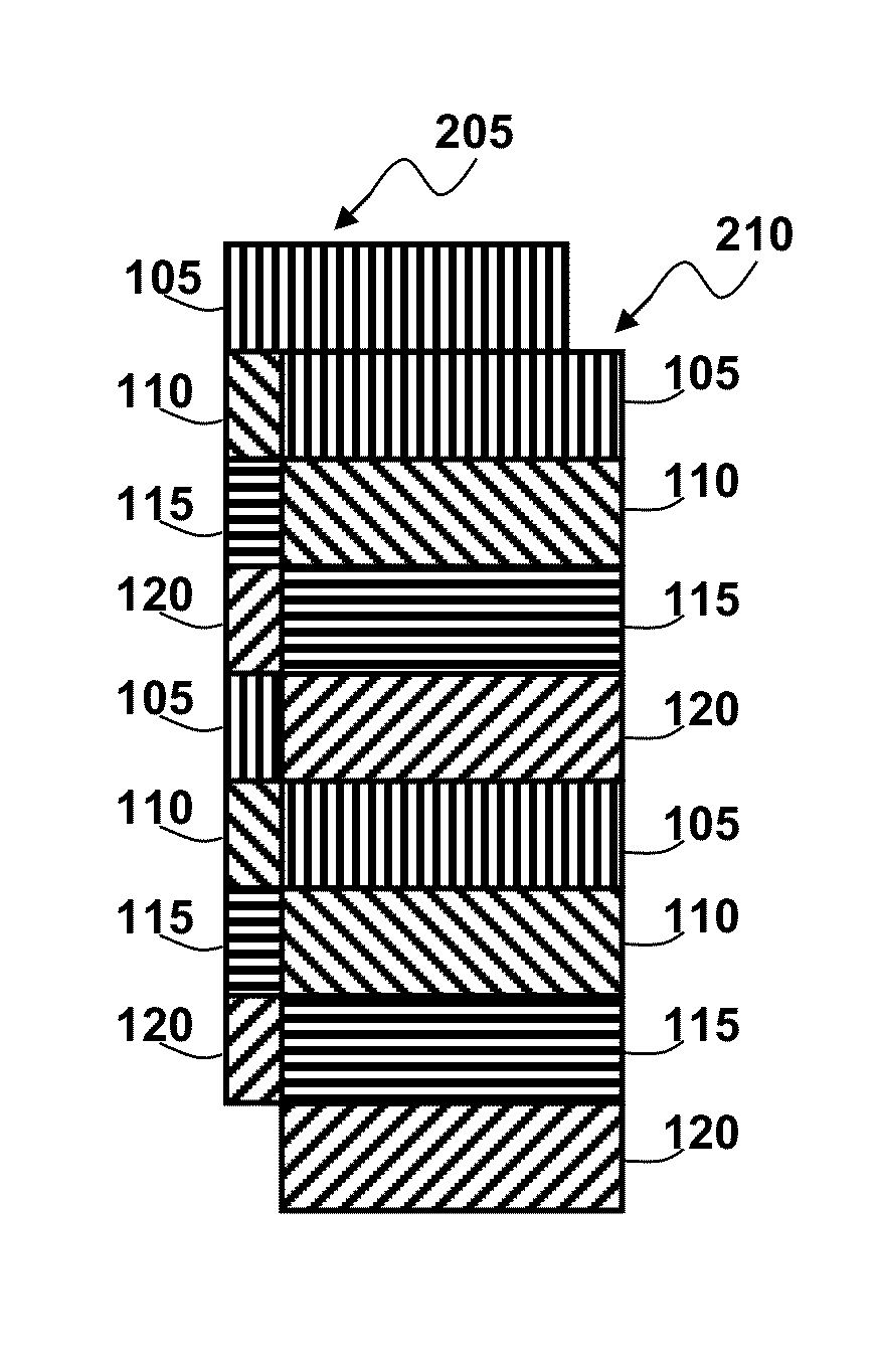
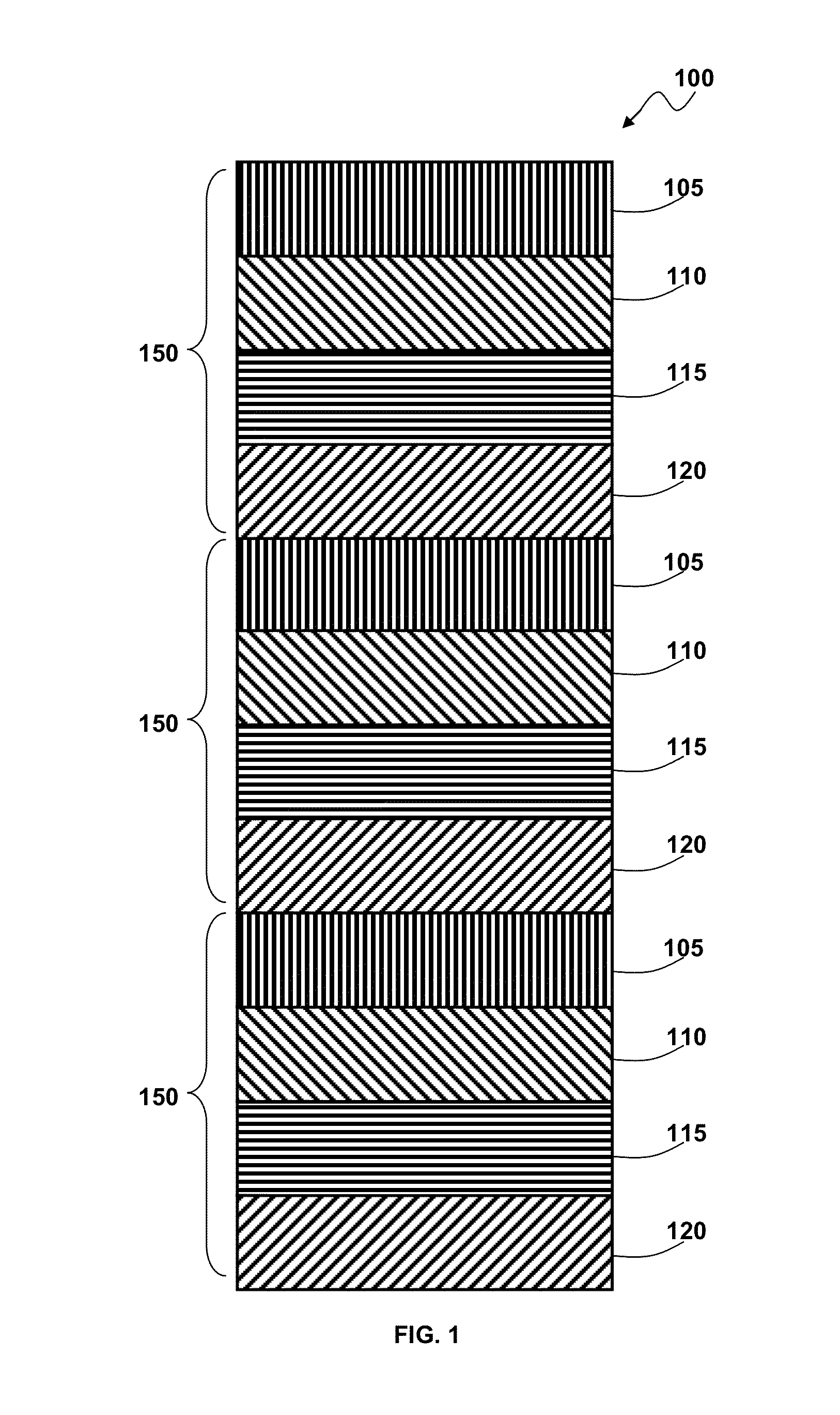
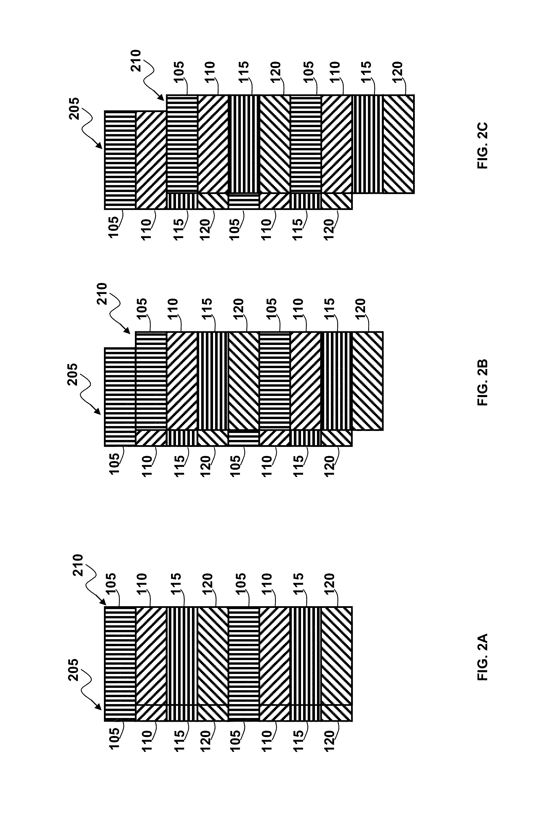
The patent text describes a way to create films that can control the amount of energy ( sunlight, heat, etc.) that is transmitted through them. These films can be used in a variety of applications, like cars, buildings, and even homes. The film is made up of many small bands of alternating polarization, which when combined can create different patterns. The orientation and spacing of these bands can be adjusted for different uses. In some cases, multiple films can be placed together to create more complex patterns that control the energy flow even better. The main benefit is that these films can help reduce the amount of energy wasted and make it easier to control how it is transmitted.

Problems solved by technology

Residential use appears to be more limited because homeowners expect to be able to vary the amount of light coming in through their windows more so than they do in their cars.
There is also the issue of privacy and security, which may not be as big of a concern in commercial buildings.
While this technology offers some reduction in glare and relief from heat from the Sun, the fact that the film is permanently affixed to the window does not offer any flexibility in the amount of light transmitted or any option for privacy.
However, most homeowners may find the cost of such systems to be prohibitive for residential applications.

Method used


Image

  • Polarized film apparatus with bands of alternating orientation
  • Polarized film apparatus with bands of alternating orientation
  • Polarized film apparatus with bands of alternating orientation

Examples


Embodiment Construction

[0025]The particular values and configurations discussed in these non-limiting examples can be varied and are cited merely to illustrate at least one embodiment and are not intended to limit the scope thereof.

[0026]The embodiments now will be described more fully hereinafter with reference to the accompanying drawings, in which illustrative embodiments of the invention are shown. The embodiments disclosed herein can be embodied in many different forms and should not be construed as limited to the embodiments set forth herein; rather, these embodiments are provided so that this disclosure will be thorough and complete, and will fully convey the scope of the invention to those skilled in the art. Like numbers refer to like elements throughout. As used herein, the term “and / or” includes any and all combinations of one or more of the associated listed items.

[0027]The terminology used herein is for the purpose of describing particular embodiments only and is not intended to be limiting o...


PUM


Abstract

A polarized film apparatus comprising printed bands of successively alternating polarization orientations is disclosed. The printed bands of alternating polarization orientations repeat throughout the length of the film. The polarized film can be installed in an object, for example a window where the amount of energy through the object has to be controlled. Two identical films are superimposed to create polarization patterns that can be varied when one film is displaced with respect to the other. The resulting variable polarization patterns can be utilized to control the amount of energy allowed through this arrangement. The polarized films with bands of alternating polarization orientations can be utilized to control the amount of energy for example sunlight, radiated heat transmission, illumination level, electromagnetic radiation, etc.

Description

CROSS-REFERENCE TO PROVISIONAL PATENT APPLICATION[0001]This patent application claims the benefit under 35 U.S.C. §119(e) of U.S. Provisional Application Ser. No. 61 / 482,086 entitled, “Polarized Film Apparatus With Bands of Alternating Orientation,” which was filed on May 3, 2011 and is incorporated herein by reference in its entirety.TECHNICAL FIELD[0002]Embodiments are generally related to polarized films. Embodiments also relate to polarized film with bands of successively alternating polarization orientations. Embodiments additionally relate to polarized films that are superimposed to create variable polarization patterns, when one film is displaced with respect to the other.BACKGROUND OF THE INVENTION[0003]Window tinting has been widely used to control glare, radiated heat transmission, and illumination levels in the automotive and commercial markets, and to some extent in the residential market. The most common example of this can be seen in automotive windows. Residential use...

Claims


Application Information

Patent Timeline
Patent Type & Authority Patents(United States)
IPC IPC(8): G02B5/30
CPCG02B5/3025
Inventor GUTIERREZ, ROBERTO
Owner INICIA IP HLDG
Learn More