Trailing edge flap

a technology of railing edge and flap, which is applied in the direction of wing adjustment, wings, transportation and packaging, etc., can solve the problems of affecting the performance the arrangement of the railing edge flap is limited to a single slot, and the performance loss at the higher deflection required for landing, etc., to achieve the effect of greater li

Active Publication Date: 2014-05-06
AIRBUS OPERATIONS LTD
View PDF35 Cites 31 Cited by
  • Summary
  • Abstract
  • Description
  • Claims
  • Application Information

AI Technical Summary

Benefits of technology

[0007]The invention is advantageous in that a simple single slotted flap arrangement can be modified with relatively few changes to provide the greater lift that may be required for higher weight aircraft variants.
[0009]The auxiliary flap element may take an aerofoil profile or a plate-like profile, for example. The plate-like profile advantageously occupies a small volume and yet provides the increased planform area desired for the flap when extended. The auxiliary flap element is preferably supported by a rail mounted to the main flap element. An actuator may be provided for moving the auxiliary flap element relative to the main flap element. Preferably, the actuator is a linear actuator. For simplicity, the actuator may be adapted to discretely move the auxiliary flap element between extended and retracted positions. Alternatively, the actuator may be adapted to infinitely vary the position of the auxiliary flap element between its extended and retracted positions.

Problems solved by technology

These are beneficial for take-off but suffer performance losses at the higher deflections required for landing.
Many multi-slotted flap arrangements are known but drop hinge flap arrangements are limited to a single slot due to their single hinge point.
Accordingly, it can be necessary for aircraft manufacturers to adopt a completely different flap arrangement for use on higher weight aircraft variants within a family, which is undesirable.

Method used


Image

  • Trailing edge flap
  • Trailing edge flap

Examples


Embodiment Construction

)

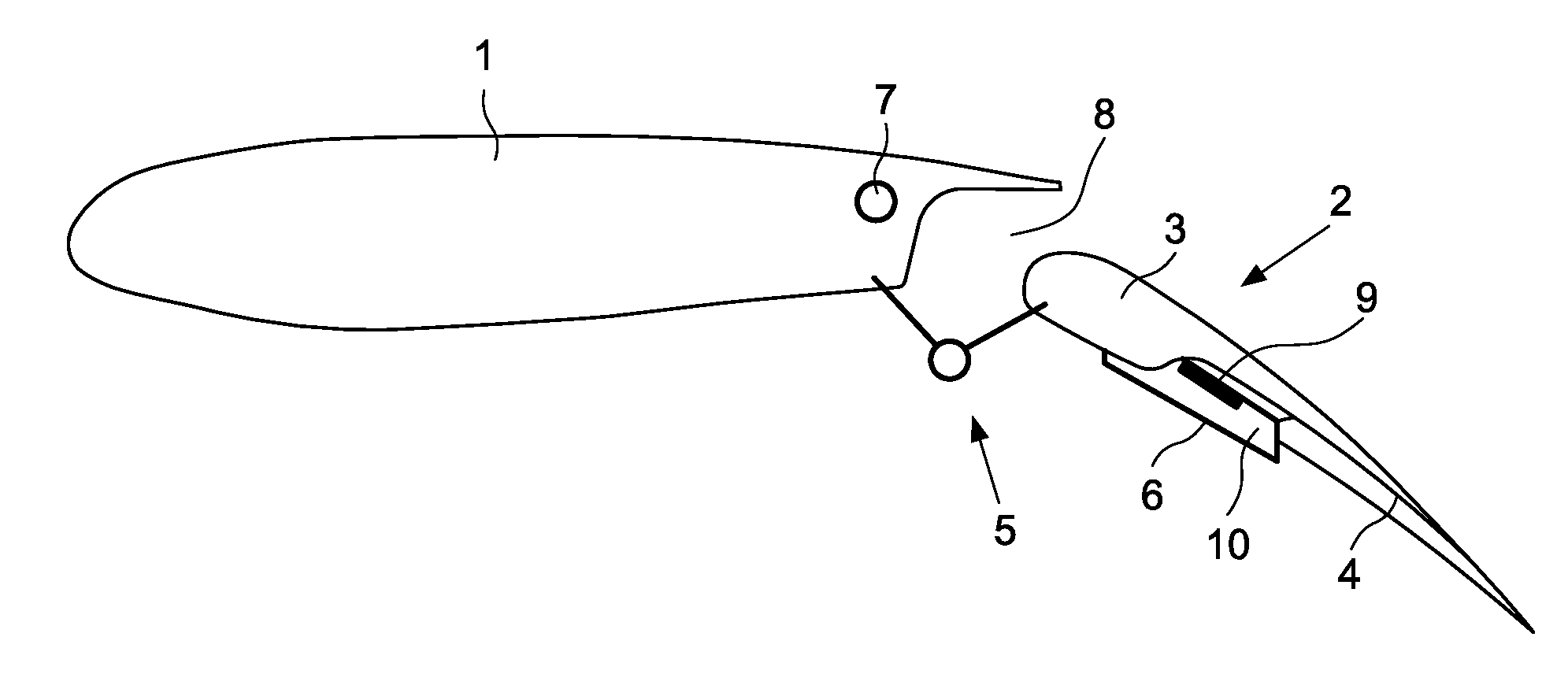
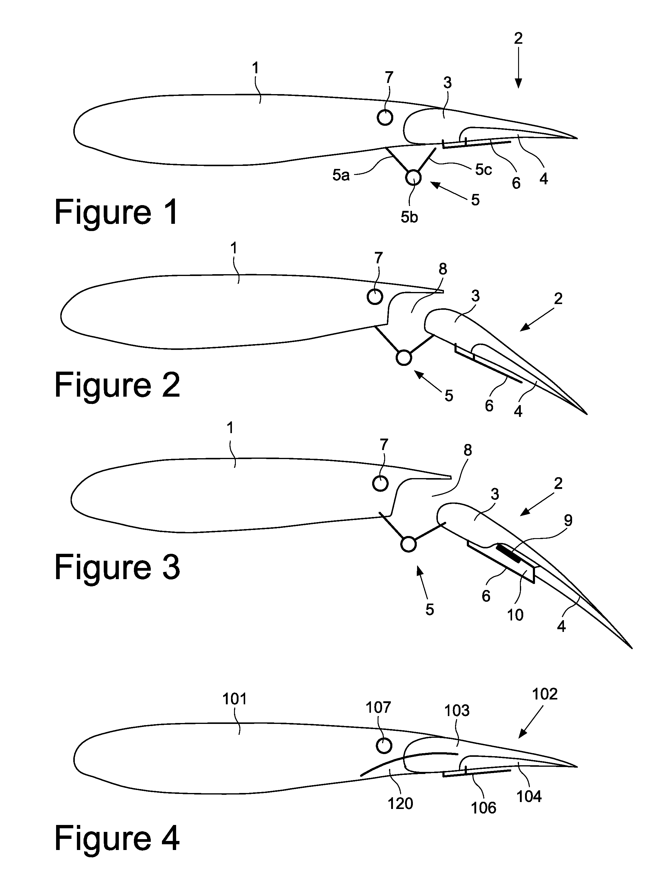
[0016]FIG. 1 shows an aircraft wing including a main fixed wing portion 1 and a single slotted trailing edge flap arrangement 2. The flap arrangement 2 includes a main element 3 and an auxiliary flap element 4 supported by the main flap element 3.

[0017]The main flap element 3 is pivotally supported from the fixed wing portion 1 by a drop hinge linkage arrangement 5. The drop hinge linkage arrangement includes a fixed strut 5a, a hinge point 5b and a drop link 5c. The fixed strut 5a is mounted to the fixed wing portion 1 and carries the hinge point 5b. The drop link 5c connects the main flap element 3 to the hinge point 5b.

[0018]The auxiliary flap element 4 is supported by a rail 6 mounted to the main flap element 3. The auxiliary flap element 4 is slidably disposed upon the rail 5 for translational movement relative to the main flap element 3.

[0019]FIG. 1 shows the flap arrangement 2 in its retracted position. The main flap element 3 is stowed, tucked against the trailing edge of ...


PUM


Abstract

A single slotted trailing edge flap arrangement for an aircraft wing, comprising a main flap element and an auxiliary flap element sealed to and supported by the main flap element for movement between a retracted and an extended position relative to the main flap element so as to vary the planform area of the flap. The auxiliary flap element remains sealed to the main flap element when in its extended position, and movement of the auxiliary flap element relative to the main flap element is solely translational. The auxiliary flap element may be translationally deployed from the main flap element by sliding the auxiliary flap element out from the underside of the main flap element. Also, a method of operating the flap arrangement.

Description

RELATED APPLICATIONS[0001]The present application is based on, and claims priority from, Great Britain Application Number 0920968.5, filed Nov. 27, 2009, the disclosure of which is hereby incorporated by reference herein in its entirety.FIELD OF THE INVENTION[0002]The present invention relates to a trailing edge flap arrangement for an aircraft wing. The invention also relates to a method of operating a trailing edge flap arrangement.BACKGROUND OF THE INVENTION[0003]Aircraft wing trailing edge flaps are high lift devices which are typically deployed on take-off and landing to increase the lift coefficient by increasing the camber of the wing aerofoil. This can be achieved by rotating the flap downwardly about its hinge line with respect to the fixed wing portion. Some flaps, for example the Fowler flap, further increase the lift generated by the wing by also increasing the planform area of the wing. This is achieved by moving the flap along a track such that the flap moves aft and r...

Claims


Application Information

Patent Timeline
Patent Type & Authority Patents(United States)
IPC IPC(8): B64C3/50B64C3/54
CPCB64C9/26
Inventor MORRIS, STUART
Owner AIRBUS OPERATIONS LTD
Why Eureka
Try Eureka