
Backlight assembly and display apparatus having the same

a technology of backlight assembly and display apparatus, which is applied in the direction of lighting and heating apparatus, planar/plate-like light guides, instruments, etc., to achieve the effect of reducing the size of the bezel, easy control of the viewing angle of the display apparatus, and easy embodied

Active Publication Date: 2014-05-06
SAMSUNG DISPLAY CO LTD
View PDF14 Cites 57 Cited by
  • Summary
  • Abstract
  • Description
  • Claims
  • Application Information

AI Technical Summary

Benefits of technology

The patent describes a display that can control the viewing angle and create a stereoscopic image. This is achieved by using a light guide plate that has a concavo-convex shape on the opposite surface to the incident surface. The light guide plate can also be divided into smaller blocks to decrease the size of the bezel.

Problems solved by technology

Light emitted from the light source in the edge illumination backlight assembly has a wide emitting angle that renders it difficult to employ the edge illumination backlight assembly for an active viewing angle liquid crystal display apparatus (LCD), a color-filterless LCD, and a stereoscopic LCD which employ collimated light having a narrow emitting angle.

Method used


Image

  • Backlight assembly and display apparatus having the same
  • Backlight assembly and display apparatus having the same
  • Backlight assembly and display apparatus having the same

Examples


Embodiment Construction

[0027]Hereinafter, exemplary embodiments of the present invention will be described in detail with reference to the accompanying drawings, wherein the same numbers may be used to denote the same or substantially the same elements throughout the drawings and the specification.

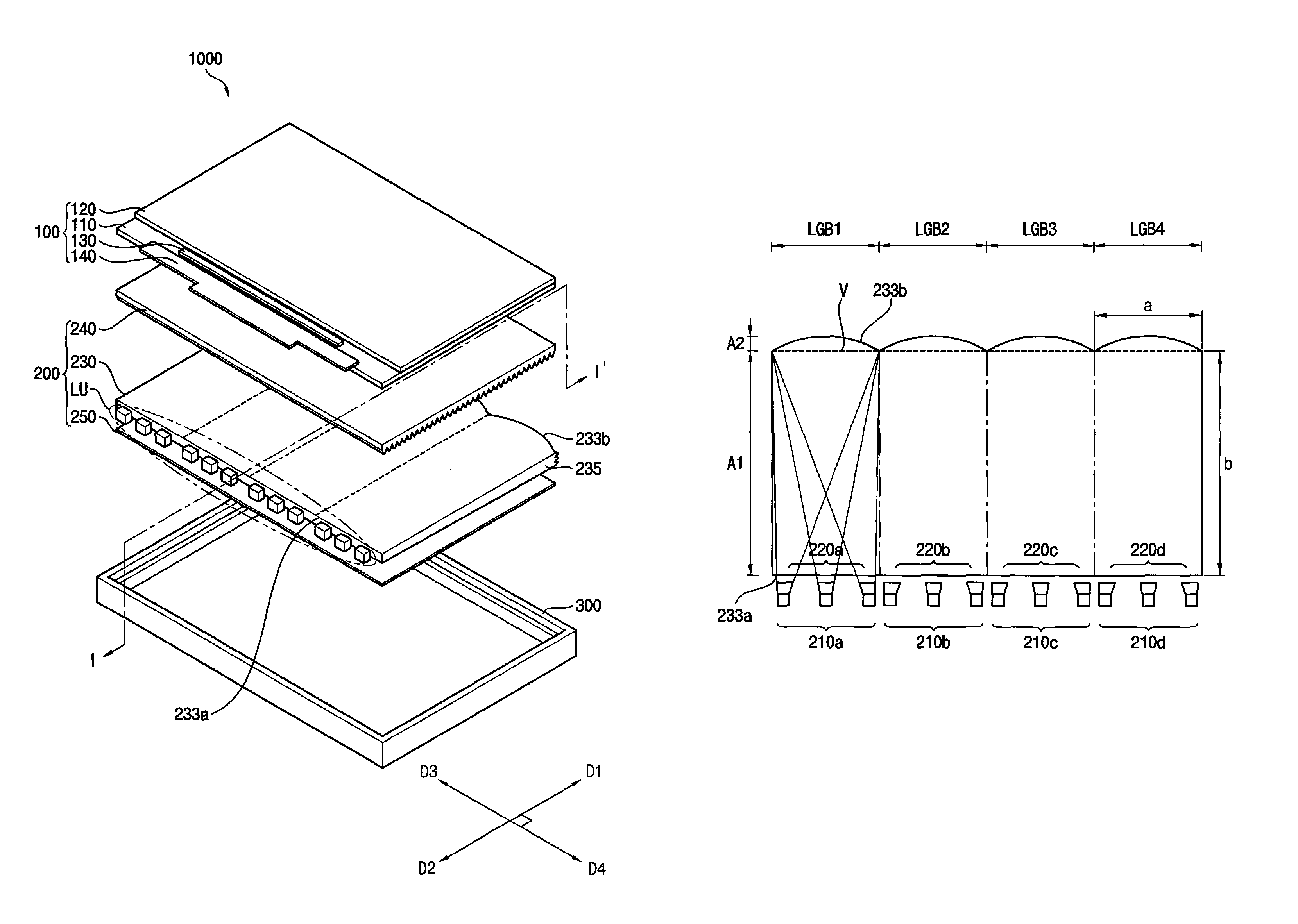
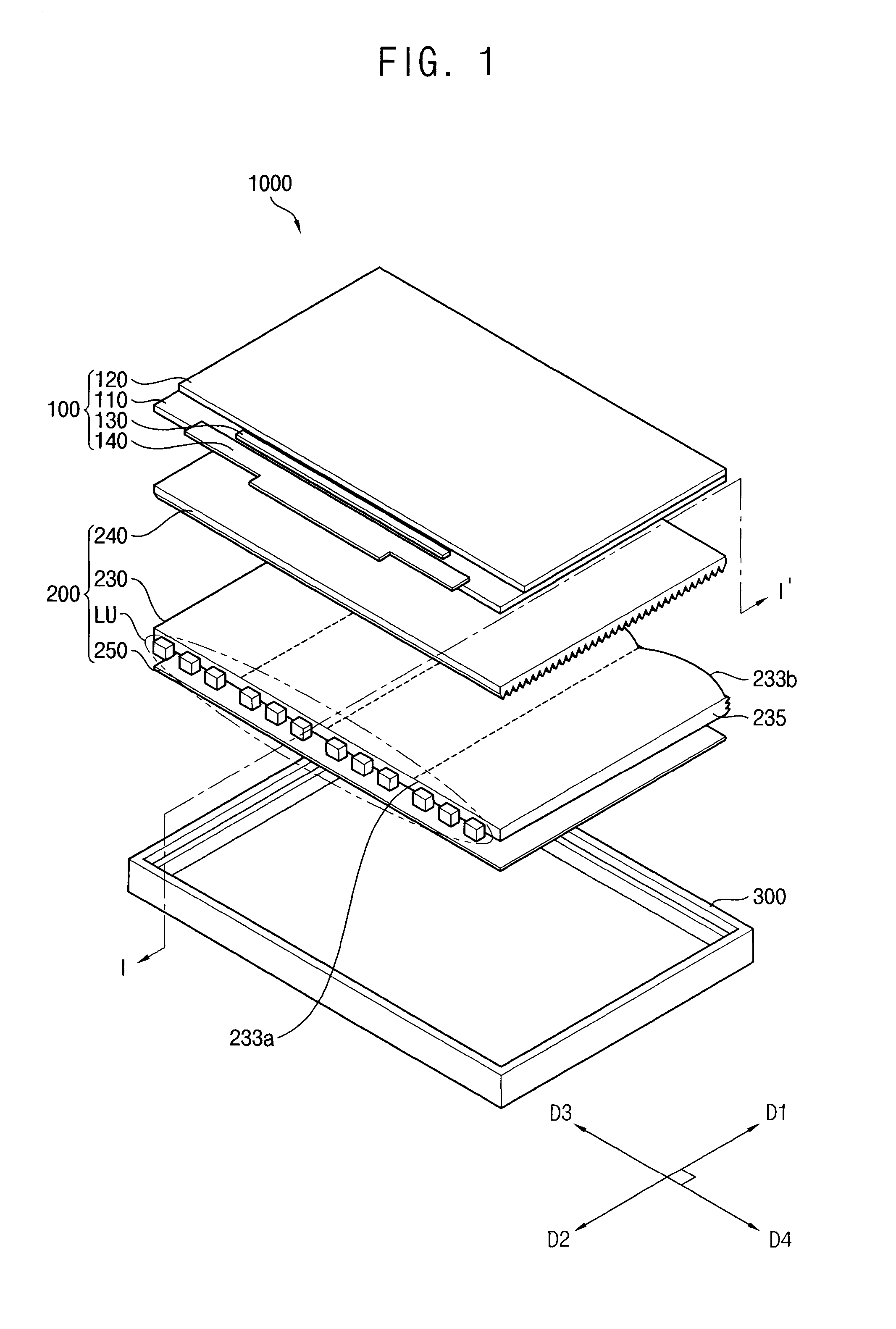
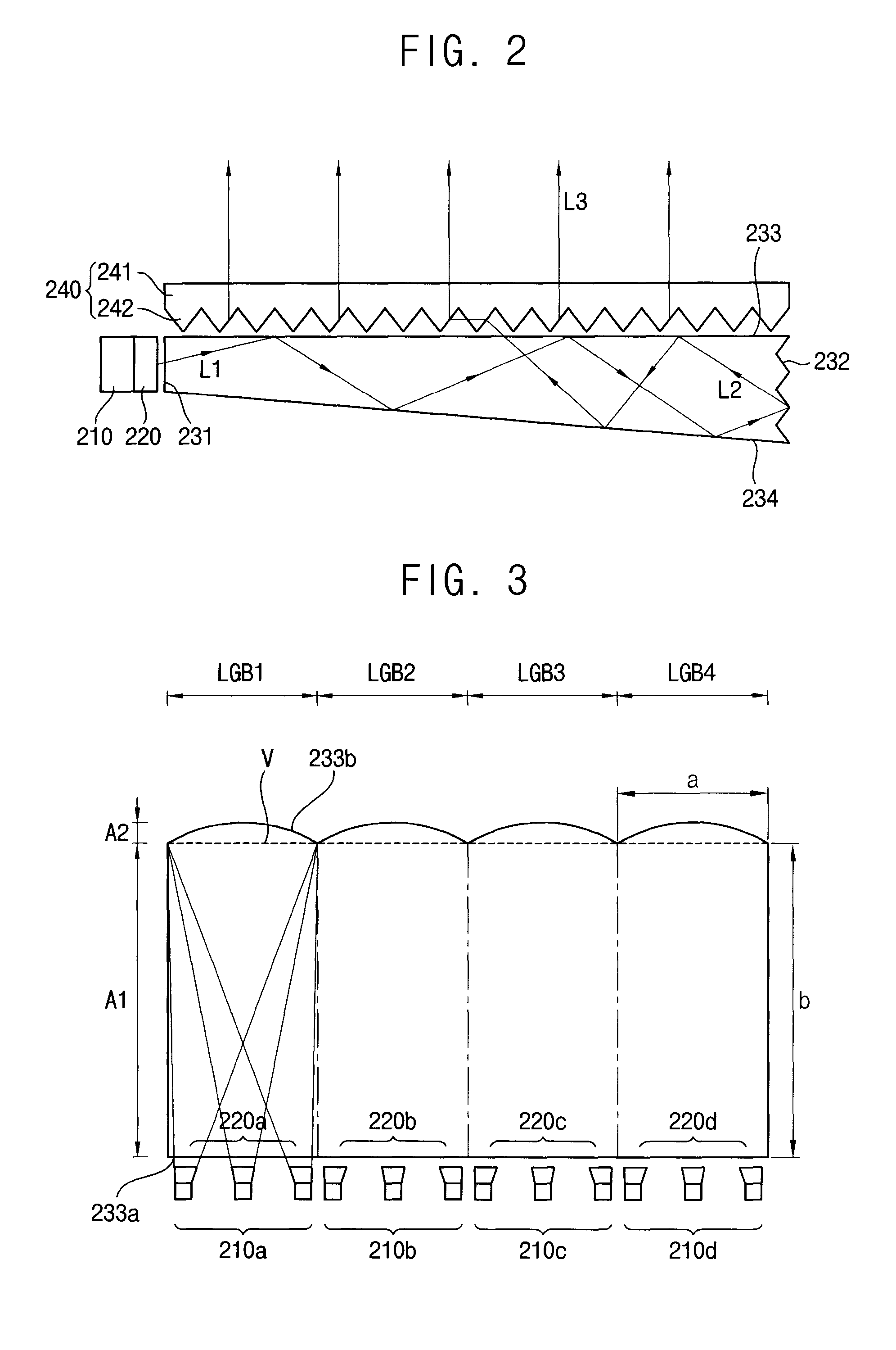
[0028]FIG. 1 is an exploded perspective view illustrating a display apparatus according to an exemplary embodiment of the present invention. FIG. 2 is a cross-sectional view taken along a line I-I′ of FIG. 1.

[0029]Referring to FIGS. 1 and 2, a display apparatus 1000 according to an embodiment of the present exemplary embodiment includes a display panel 100, a backlight assembly 200, and a receiving container 300.

[0030]The display panel 100 includes a first substrate 110, a second substrate 120 opposite to the first substrate 110, a driving part 130 that drives gate lines (not shown) and data lines (not shown) and is formed between the first and second substrates 110 and 120, and a printed circuit board 140. The ...


PUM


Abstract

The backlight assembly includes a light source part and a light guide plate. The light source part generates a first light beam. The light guide plate has a plurality of light guide blocks. Each of the light guide blocks has a light incident surface, an opposite surface, a light emitting surface, and an inclined surface. The light incident surface receives the first light beam. The opposite surface is located opposite to the light incident surface, has a convex shape with respect to the light incident surface, and reflects the first light beam and converts the first light beam into a second light beam. The light emitting surface emits the second light beam. The inclined surface is inclined with respect to the light emitting surface.

Description

CROSS-REFERENCE TO RELATED APPLICATION[0001]This application claims priority under 35 U.S.C. §119 to Korean Patent Application No. 2010-106422, filed on Oct. 29, 2010 in the Korean Intellectual Property Office (KIPO), the contents of which are herein incorporated by reference in their entirety.BACKGROUND[0002]1. Technical Field[0003]Exemplary embodiments of the present invention relate to a backlight assembly and a display apparatus having the backlight assembly. More particularly, exemplary embodiments of the present invention relate to a backlight assembly providing collimated light and a display apparatus having the backlight assembly.[0004]2. Discussion of the Related Art[0005]Generally, a display apparatus includes a display panel and a backlight assembly. Backlight assemblies are classified into direct-illumination backlight assemblies directly providing the display panel with light and edge-illumination backlight assemblies providing the display panel with light through a lig...

Claims


Application Information

Patent Timeline
Patent Type & Authority Patents(United States)
IPC IPC(8): F21V7/04
CPCG02B6/0046G02B6/0053G02B6/002G02B6/003G02B6/0078
Inventor KIM, GUK-HYUNLEE, MOON-GYUIM, HYUN-DEOK
Owner SAMSUNG DISPLAY CO LTD
Learn More