Optimizing energy transmission in a leadless tissue stimulation system

a tissue stimulation and energy transmission technology, applied in the field of optimizing acoustic or ultrasound energy transmission and energy conversion in implantable devices, can solve problems such as inefficiency, and achieve the effects of efficient transmission of energy, efficient acoustic energy delivery, and improved system operation efficiency

Active Publication Date: 2014-05-06
EBR SYST
View PDF93 Cites 386 Cited by
  • Summary
  • Abstract
  • Description
  • Claims
  • Application Information

AI Technical Summary

Benefits of technology

[0011]Systems and methods are provided for efficiently delivering acoustic energy from an implanted or externally applied acoustic transmitter to an implanted acoustic receiver. The acoustic energy is converted by the receiver into electrical energy which can be used for a variety of purposes. The electrical energy will typically be delivered to electrodes in contact with tissue in order to stimulate tissue, for example, in cardiac pacing for bradycardia, for termination of tachyarrhythmia, for bi-ventricular resynchronization therapy for heart failure, or the like. The systems and methods of the present invention could also be used in a variety of other applications, including applications for nerve stimulation, brain stimulation, voluntary muscle stimulation, gastric stimulation, bone growth stimulation, pain amelioration, sensing and communication of local diagnostic information, and the like, where an acoustic transmitter has to efficiently transmit energy to an implanted receiver. The implanted acoustic receiver could act as a tissue stimulator (receiver-stimulator) or act more generally as an acoustic energy converter (receiver-converter). Efficient transmission can be achieved by deploying strategies for locating the receiver and then transmitting a focused acoustic beam specifically aimed at the receiver and thereby improving operational efficiency of the system. These systems and methods are particularly useful when the transmitter is an implantable device dependent on a limited source of energy, such as a battery.
[0013]By “location signal” we mean a signal that is either passively or actively generated by the receiver-stimulator. The location signal may be in response to a “locator signal” transmitted by the controller-transmitter or may be periodically transmitted by the receiver-stimulator. The location signal is used by the controller-transmitter to determine the location of the receiver relative to the controller-transmitter, thus allowing the controller-transmitter to direct a focused, efficient acoustic beam at the receiver-stimulator.
[0015]Another exemplary embodiment of the invention described herein is a system for stimulating tissue comprising an implantable acoustic controller-transmitter comprising an array of acoustic transducers configured to transmit focused acoustic energy; one or more implantable acoustic receiver-stimulators adapted to receive the acoustic energy and convert the acoustic energy into electrical energy, wherein the receiver-stimulator further comprises electrodes configured to be in electrical communication with the tissue; and the electrical energy is delivered between the electrodes; and wherein the controller-transmitter is configured to determine the location of one or more of the receiver-stimulators relative to the controller-transmitter so that the controller-transmitter can direct the focused acoustic energy to one or more of the receiver-stimulators.

Problems solved by technology

If applied directly to the tissue this AC electrical power does not stimulate the tissue because its frequency is too high for excitation / stimulation.
However, in this mode of operation most of the transmitted acoustic energy may pass by the receiver-stimulator and not used efficiently.

Method used


Image

  • Optimizing energy transmission in a leadless tissue stimulation system
  • Optimizing energy transmission in a leadless tissue stimulation system
  • Optimizing energy transmission in a leadless tissue stimulation system

Examples


Embodiment Construction

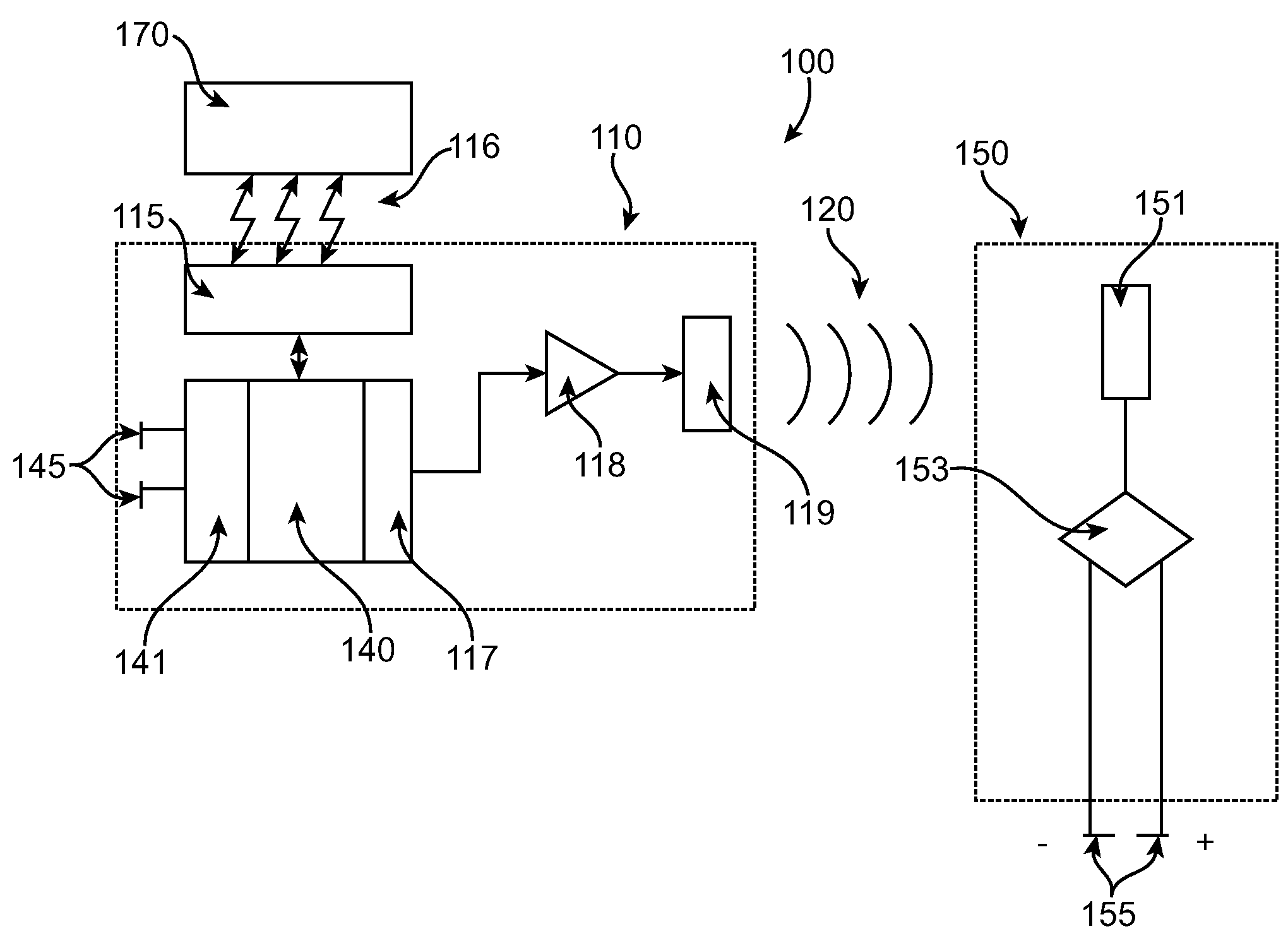
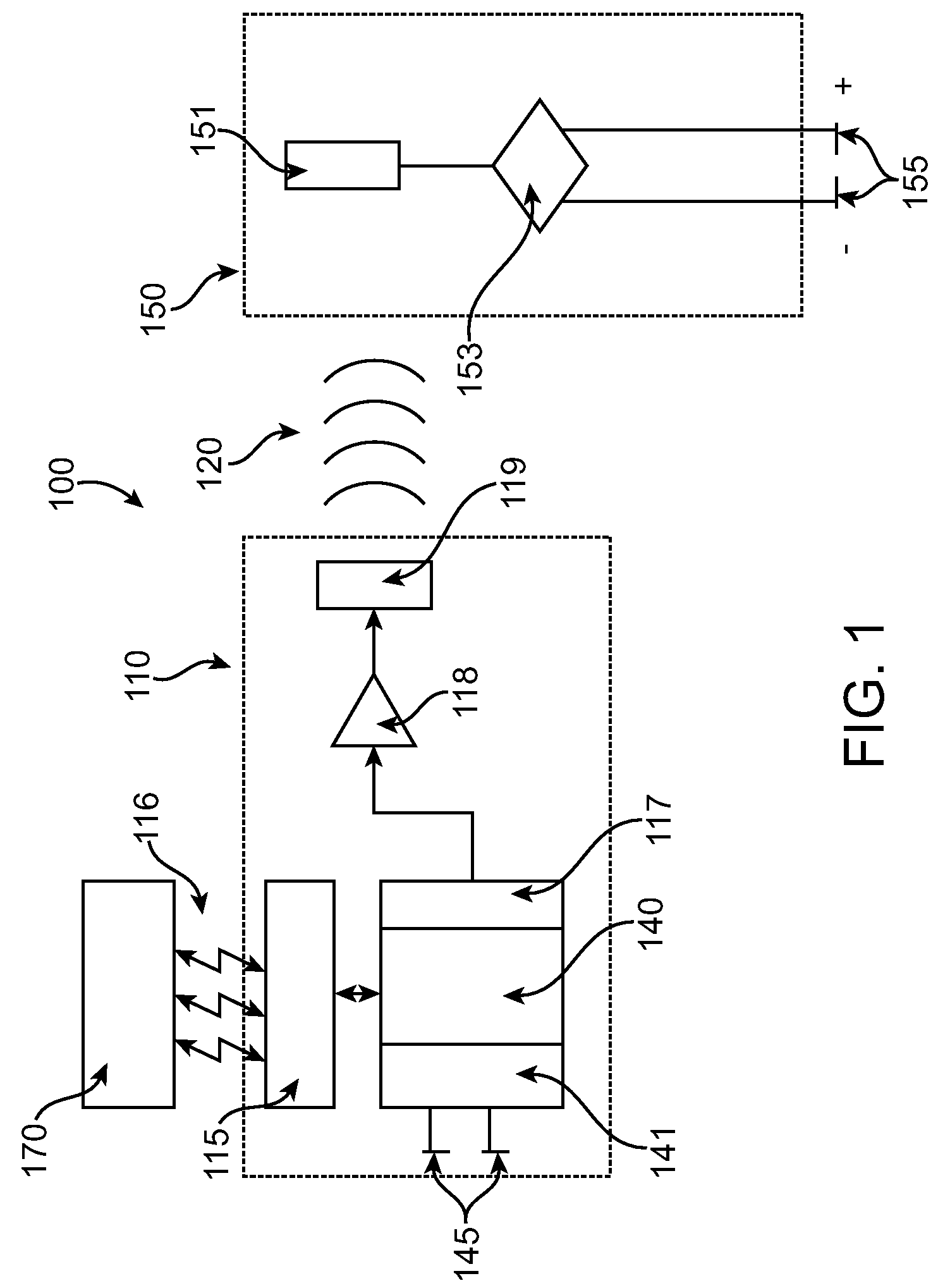
[0027]A leadless tissue stimulation system is shown in FIG. 1 as system 100. An implantable or external controller-transmitter module 110 generates acoustic waves 120 of sufficient amplitude and frequency and for a duration and period such that the receiver-stimulator module 150 electrically stimulates tissue. An external programmer 170 wirelessly communicates with an implantable controller-transmitter module 110, typically by radio frequency telemetry means 116, to adjust operating parameters. The implantable controller-transmitter module comprises a telemetry receiver 115 for adjusting the transmit acoustic characteristics, control circuitry 140 and signal generator 117, a power amplifier 118, and an output transducer assembly 119 for generating the acoustic beam 120 transmitted to receiver-stimulator 150. Understandably, the controller-transmitter 110 transfers acoustic energy to the receiver-stimulator 150 leadlessly. Control circuitry 140 contains an electrical signal sensing c...


PUM


Abstract

Method and systems for optimizing acoustic energy transmission in implantable devices are disclosed. Transducer elements transmit acoustic locator signals towards a receiver assembly, and the receiver responds with a location signal. The location signal can reveal information related to the location of the receiver and the efficiency of the transmitted acoustic beam received by the receiver. This information enables the transmitter to target the receiver and optimize the acoustic energy transfer between the transmitter and the receiver. The energy can be used for therapeutic purposes, for example, stimulating tissue or for diagnostic purposes.

Description

CROSS-REFERENCES TO RELATED APPLICATIONS[0001]The subject matter of this application is related to that of the following commonly owned patent applications: Ser. No. 11 / 315,524, Ser. No. 11 / 535,857, Ser. No. 11 / 315,023. The full disclosures of each of these prior filings are incorporated herein by reference but the benefit of the filing dates is not being claimed.FIELD OF THE INVENTION[0002]This invention generally relates to optimizing acoustic or ultrasound energy transmission and energy conversion and more particularly to optimizing acoustic energy transmission and conversion in implantable devices.BACKGROUND OF THE INVENTION[0003]Stimulation of cardiac tissue using a leadless cardiac stimulation system has been disclosed earlier by the applicant. Generally, such a system comprises an arrangement of one or more acoustic transducers, and associated circuitry, referred to as a controller-transmitter, and one or more implanted receiver-stimulator devices. The controller-transmitter ...

Claims


Application Information

Patent Timeline
Patent Type & Authority Patents(United States)
IPC IPC(8): A61N1/378A61N1/18
CPCA61N1/37217A61N1/3756A61N1/37235A61N1/3787A61N1/37252A61B5/0093
Inventor WILLIS, N. PARKERBRISKEN, AXEL F.COWAN, MARK W.PARE, MICHAELFOWLER, ROBERTBRENNAN, JAMES
Owner EBR SYST
Why Eureka
Try Eureka