
Method and system for locating a hand-held terminal

a technology of hand-held terminals and methods, applied in the direction of instruments, measurement devices, indirect connection of subscribers, etc., can solve the problems of loss of satellite signals in any warehouse with a metal roof, time-consuming and laborious approaches, and expensive solutions

Active Publication Date: 2014-05-13
PSION
View PDF14 Cites 7 Cited by
  • Summary
  • Abstract
  • Description
  • Claims
  • Application Information

AI Technical Summary

Benefits of technology

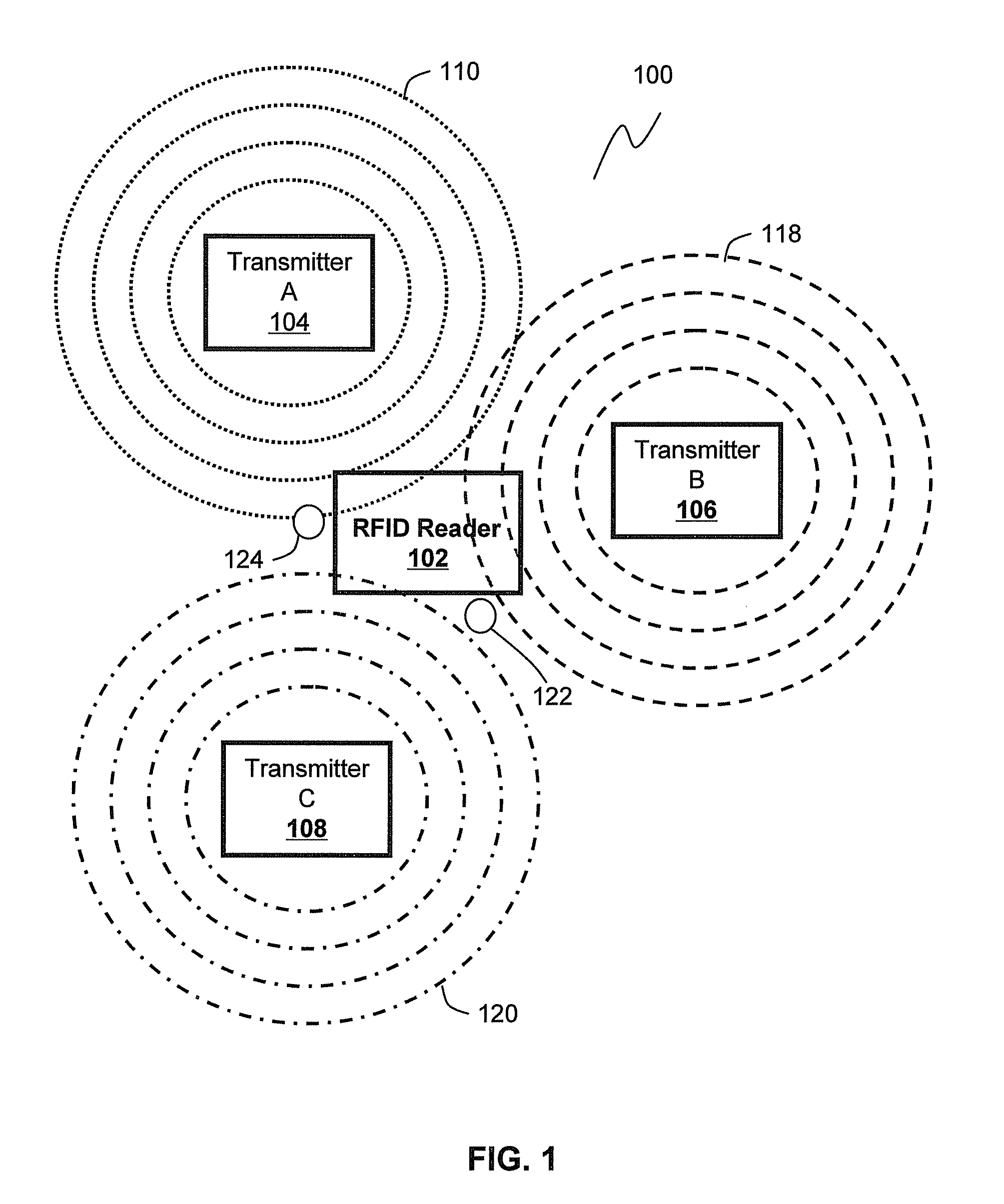
[0006]Preferably, each unique RFID pseudo tag signal in the sequence has a progressively weaker signal and therefore a progressively shorter range of transmission such that the number of unique RFID pseudo tags received by the RFID reader is inversely proportional to its distance from the transmitter.

Problems solved by technology

However, this approach can be time consuming and is subject to operator error and / or misuse.
This is an expensive solution with many drawbacks including the loss of the satellite signal in any warehouse with a metal roof.
An additional drawback is that the number of hand-held terminals, for example, radio frequency identification (RFID) readers on the market that are capable of accepting a GPS card is also quite limited.

Method used


Image

  • Method and system for locating a hand-held terminal
  • Method and system for locating a hand-held terminal
  • Method and system for locating a hand-held terminal

Examples


Embodiment Construction

[0030]Reference will now be made in detail to some specific embodiments of the invention including the best modes contemplated by the inventors for carrying out the invention. Examples of these specific embodiments are illustrated in the accompanying drawings. While the invention is described in conjunction with these specific embodiments, it will be understood that it is not intended to limit the invention to the described embodiments. On the contrary, it is intended to cover alternatives, modifications, and equivalents as may be included within the spirit and scope of the invention as defined by the appended claims. In the following description, numerous specific details are set forth in order to provide a thorough understanding of the present invention. The present invention may be practiced without some or all of these specific details. In other instances, well-known process operations have not been described in detail in order not to unnecessarily obscure the present invention....


PUM


Abstract

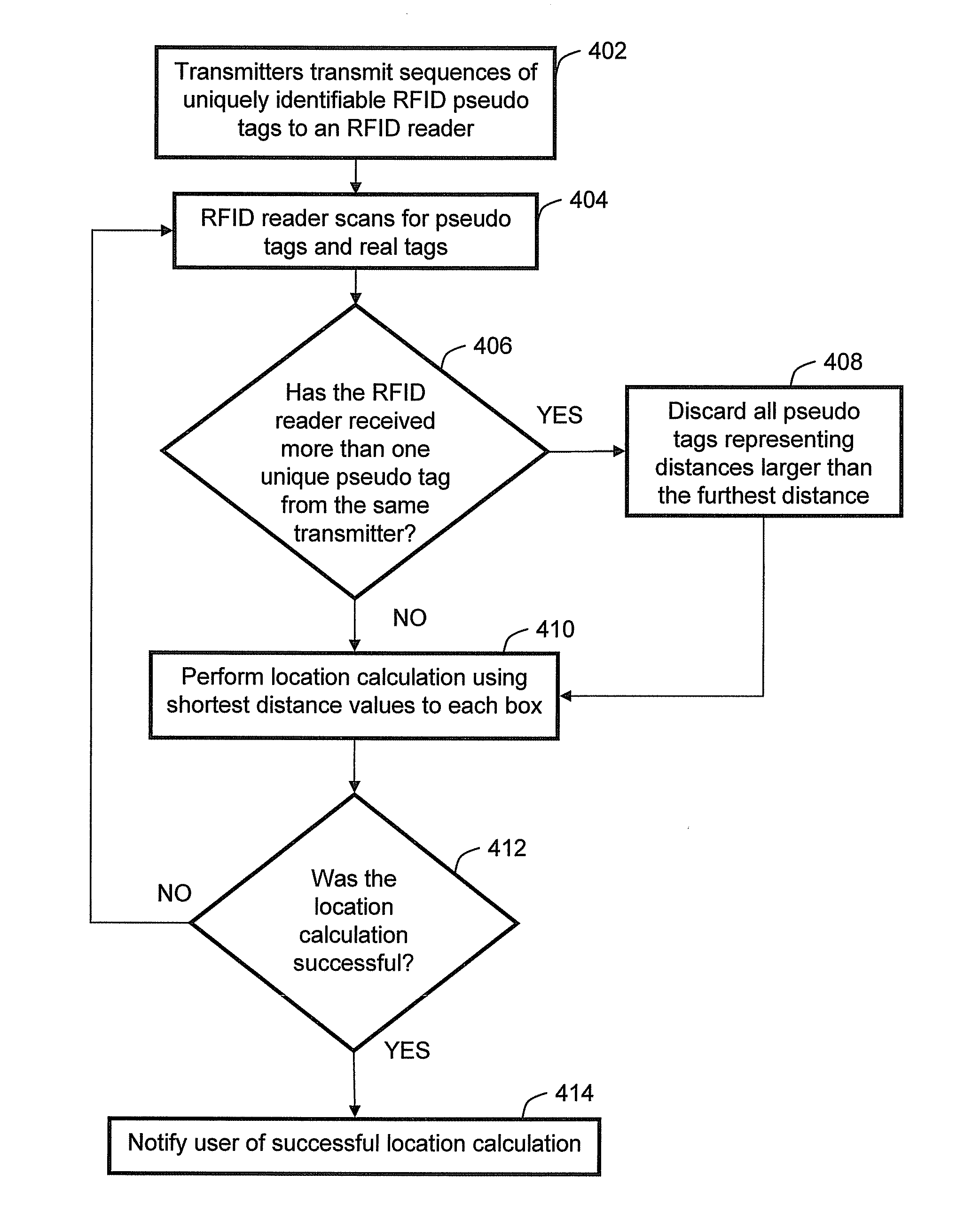
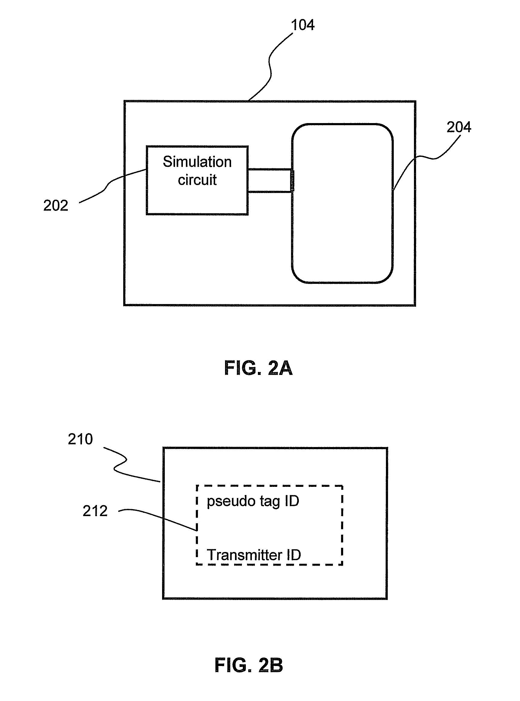
A system and a method for determining the location of an RFID reader is provided. The system includes a plurality of transmitters which have a known reference point. Each transmitter includes a circuit for transmitting a sequence of unique RFID pseudo tag signals. Each unique RFID pseudo signal in the sequence has a unique range of transmission. Each unique RFID pseudo tag in the sequence has a tag identification indicating the range of transmission of the pseudo tag signal and a transmitter identification value indicating the transmitter from which the pseudo tag signal was transmitted. An RFID reader receives the unique RFID pseudo tag signals and distinguishes between each received unique RFID pseudo tag signal. A location calculator calculates the location of the RFID reader based on the information received.

Description

FIELD OF INVENTION[0001]The present invention relates to hand-held terminals and more specifically relates to the determination of the location of a hand-held terminal.BACKGROUND OF THE INVENTION[0002]In warehousing applications, knowing the whereabouts of a reader such as a hand-held terminal when it scans a product can be very important. The classic solution involves barcoding or tagging key locations in the warehouse, and getting the operator of the hand-held terminal to scan one of these codes after scanning a product. This is a reasonably effective and cheap approach to the determination of the location of the hand-held terminal. However, this approach can be time consuming and is subject to operator error and / or misuse. An alternative approach is to fit each hand-held terminal with a global positioning system (GPS). This is an expensive solution with many drawbacks including the loss of the satellite signal in any warehouse with a metal roof. An additional drawback is that the...

Claims


Application Information

Patent Timeline
Patent Type & Authority Patents(United States)
IPC IPC(8): H04Q5/22
CPCG01S11/06G01S5/14
Inventor ATTEW, VERNON, JON
Owner PSION
Learn More