Optically transduced MEMS gyro device

a gyroscope and optical transducer technology, applied in the field of vibration gyroscopes, can solve the problems of tens of microns, large capacitance coupling factor, and difficulty in fabricating proof mass having large mass and large capacitance, and achieve high sensitivity, low cross-talk, and high sensitivity

Active Publication Date: 2014-05-20
NAT TECH & ENG SOLUTIONS OF SANDIA LLC
View PDF12 Cites 26 Cited by
  • Summary
  • Abstract
  • Description
  • Claims
  • Application Information

AI Technical Summary

Benefits of technology

The present invention provides a bulk micromachined vibratory gyro with a large proof mass and high inertial sensitivity. The gyro utilizes multi-layer sub-wavelength gratings for optical displacement transduction with high sensitivity and low cross-talk. The vibratory gyro also includes a plurality of multi-layer sub-wavelength gratings for measuring motion of the proof mass induced by drive forces and/or moments and induced by the Coriolis Effect when the gyro experiences a rotation. Additionally, the vibratory gyro includes at least one capacitive drive element and a plurality of drive electrodes for capacitively imparting the drive force to the proof mass. The invention also includes a method for maximizing orthogonality of the drive and sense modes to further reduce cross-talk.

Problems solved by technology

The technical problem addressed in this patent text is the difficulty in fabricating a proof mass for a vibratory gyroscope with large mass and capacitive coupling factor using advanced thin film techniques. The limited mass dimensions in the thickness direction and the finite surface area available in a given substrate and/or stress in the thin films make it difficult to achieve advantageous performance metrics. Deep substrate etches have been utilized in bulk micromachining techniques but anisotropic etch performance limits lateral dimensions of deep trenches to many tens of microns, which significantly limits capacitive coupling.

Method used


Image

  • Optically transduced MEMS gyro device
  • Optically transduced MEMS gyro device
  • Optically transduced MEMS gyro device

Examples


Embodiment Construction

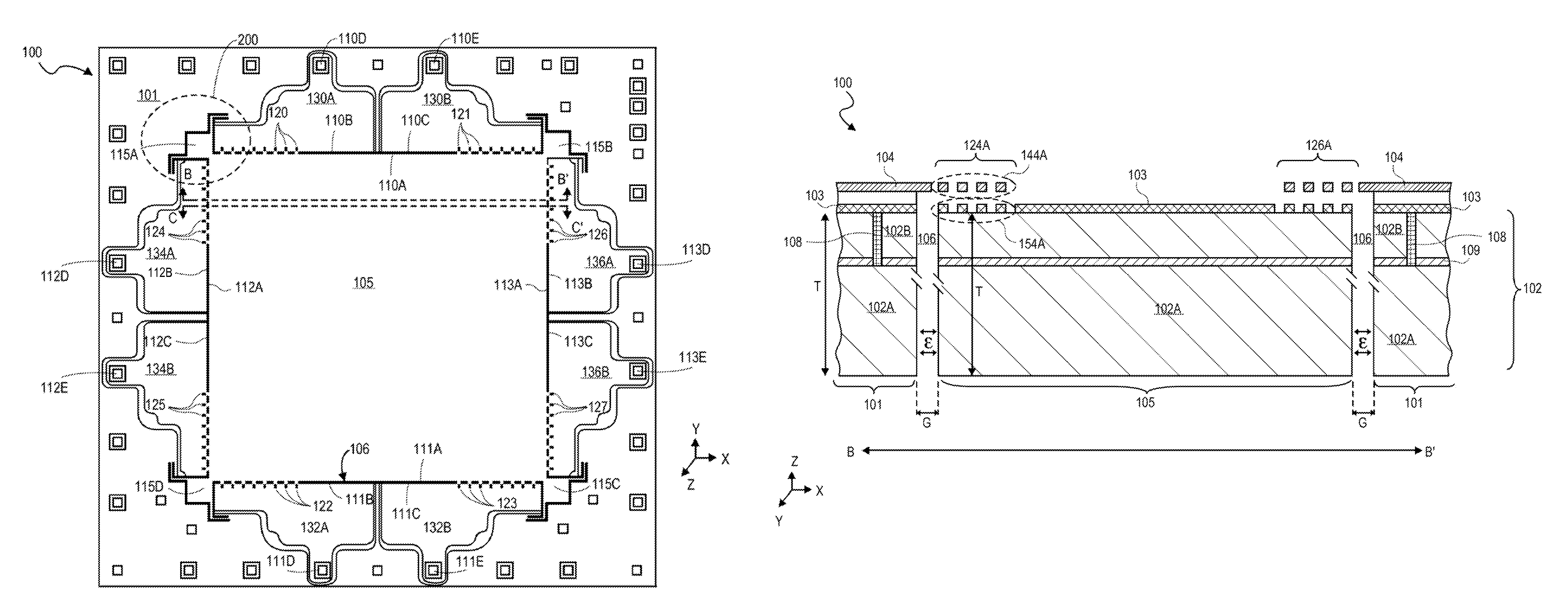
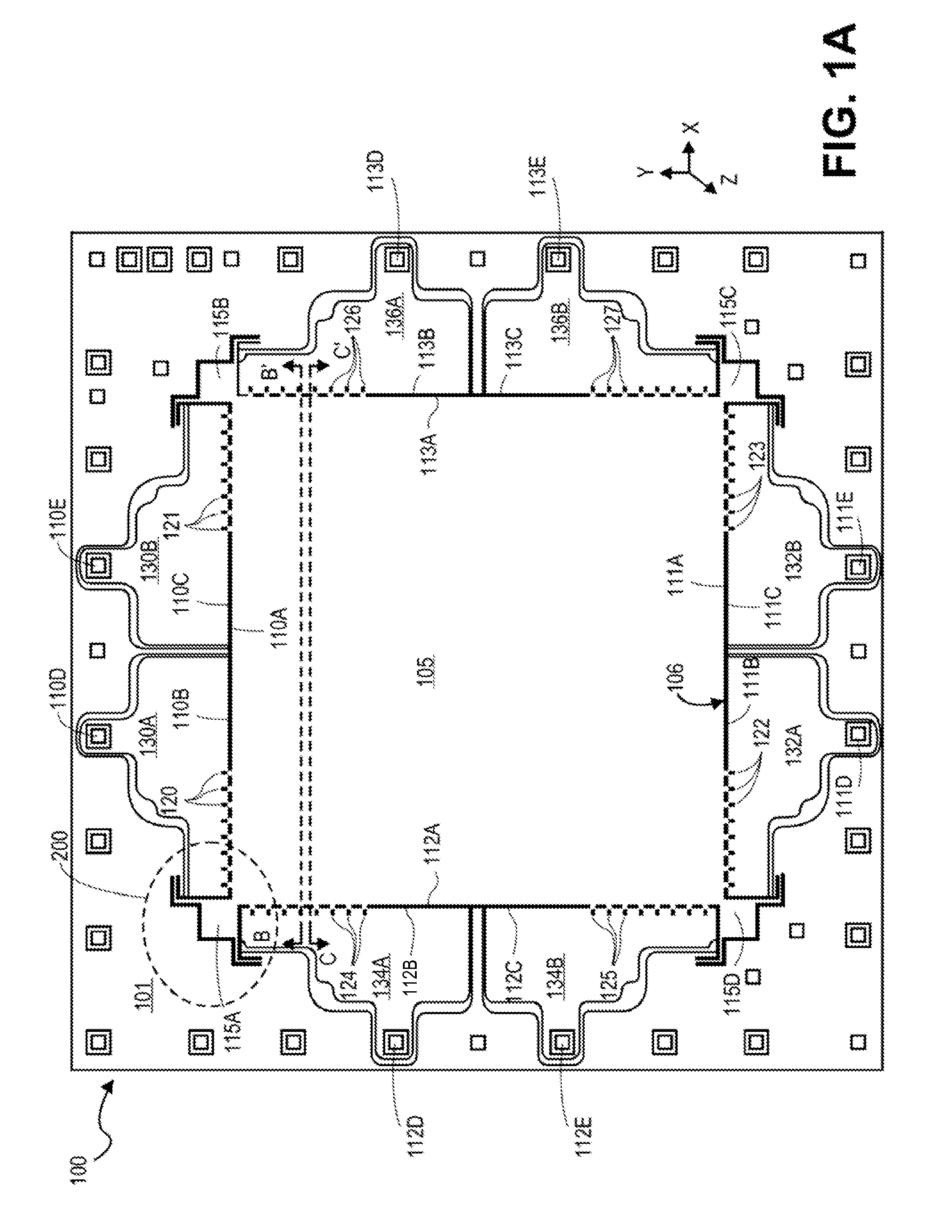
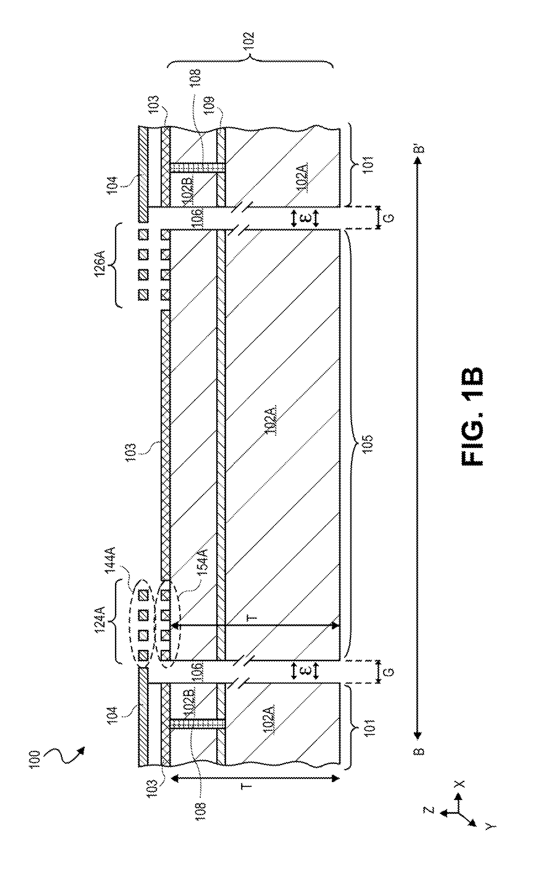
[0019]Described herein are bulk micromachined vibratory gyros. In the following description, numerous details are set forth, however, it will be apparent to one skilled in the art, that the present invention may be practiced without these specific details. In some instances, well-known methods and devices are shown in block diagram form, rather than in detail, to avoid obscuring the present invention. Reference throughout this specification to “an embodiment” means that a particular feature, structure, function, or characteristic described in connection with the embodiment is included in at least one embodiment of the invention. Thus, the appearances of the phrase “in an embodiment” in various places throughout this specification are not necessarily referring to the same embodiment of the invention. Furthermore, the particular features, structures, functions, or characteristics may be combined in any suitable manner in one or more embodiments. For example, a first embodiment may be ...


PUM


Abstract

A bulk micromachined vibratory gyro in which a proof mass has a bulk substrate thickness for a large mass and high inertial sensitivity. In embodiments, optical displacement transduction is with multi-layer sub-wavelength gratings for high sensitivity and low cross-talk with non-optical drive elements. In embodiments, the vibratory gyro includes a plurality of multi-layer sub-wavelength gratings and a plurality of drive electrodes to measure motion of the proof mass induced by drive forces and/or moments and induced by the Coriolis Effect when the gyro experiences a rotation. In embodiments, phase is varied across the plurality gratings and a multi-layer grating having the best performance is selected from the plurality.

Description


Claims


Application Information

Patent Timeline
Owner NAT TECH & ENG SOLUTIONS OF SANDIA LLC
Why Eureka
Try Eureka