Thermo-magnetic actuator

a technology of magnetizing actuators and actuators, which is applied in the direction of magnets, machines/engines, magnets, etc., can solve the problems of unsatisfactory electrical power consumption to keep the piston rod extended, and the amount of electrical power supplied

Inactive Publication Date: 2007-11-29
THERMOTION ACQUISITION
View PDF7 Cites 23 Cited by
  • Summary
  • Abstract
  • Description
  • Claims
  • Application Information

AI Technical Summary

Benefits of technology

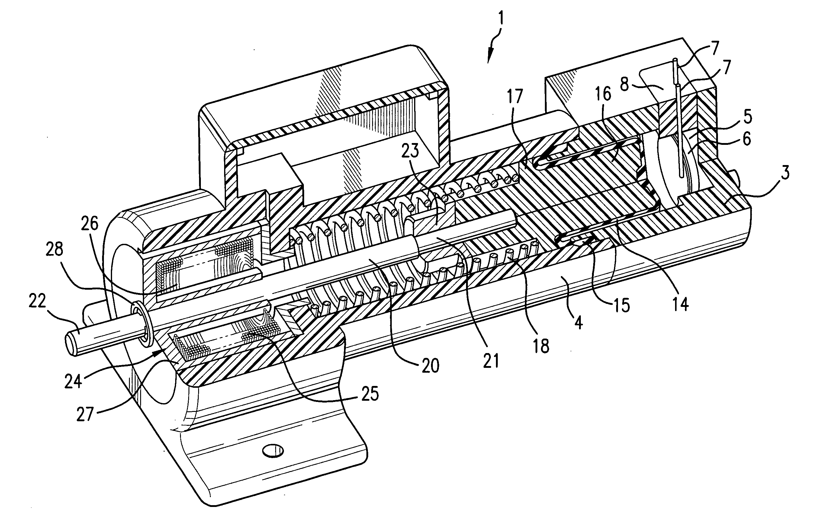
[0007]In one embodiment of the invention, the ferromagnetic target assembly includes a ferromagnetic collar attached to the piston rod. The ferromagnetic collar is held near the electromagnet by a magnetic field produced by the electromagnet, after the piston rod has reached the extended position. The piston rod reaches the extended position by the application of electrical power to the heater and driving of the piston by the expanding working fluid. Even after withdrawal of electrical power from the heater, the piston rod remains in the extended position until termination of electrical current flow to the electromagnet. Then, the ferromagnetic target assembly is no longer attracted by the electromagnet and the piston rod returns to the retracted position.
[0008]In a preferred embodiment of the invention, the ferromagnetic target assembly has a larger ferromagnetic mass than the ferromagnetic collar. The ferromagnetic target assembly in that embodiment includes a ferromagnetic target core to which the piston rod is attached and a tubular flange, preferably of a ferromagnetic material. The target core may also include a guide pin projecting coaxially with and opposite in direction from the piston rod and received within the piston. A second spring biases the piston and diaphragm away from the target core. The second spring urges the piston and the diaphragm to the same positions they occupy when the heater of the thermo-magnetic actuator is not energized, even while the ferromagnetic target assembly is held by magnetic attraction through the magnetic field produced by the electromagnet. In that situation, with no electrical current supplied to the heater, the piston rod remains in the extended position until electrical current is no longer supplied to the electromagnet.
[0009]Preferably, a control circuit controls the electrical current supplied to the heater to move the piston rod from the retracted position to the extended position. A position detector mounted on the actuator detects the position of the piston rod. The position detector includes a permanent magnet mounted on the ferromagnetic target assembly and a Hall-effect sensor that may be mounted on the housing responds to the permanent magnet when the piston rod is in the extended position. The control circuit uses the output of the Hall-effect sensor to terminate electrical current flow to the heater upon detection of the extended position of the piston rod, without interruption in electrical current flow to the electromagnet, so that the piston rod remains in the extended position, without current flow to the heater, until electrical current flow to the electromagnet is terminated.

Problems solved by technology

In some applications, the continuing consumption of electrical power to keep the piston rod extended is undesirable and at least a reduction in the amount of electrical power supplied to maintain the extension of the piston rod is, in many applications, highly desirable

Method used


Image

  • Thermo-magnetic actuator
  • Thermo-magnetic actuator
  • Thermo-magnetic actuator

Examples


Embodiment Construction

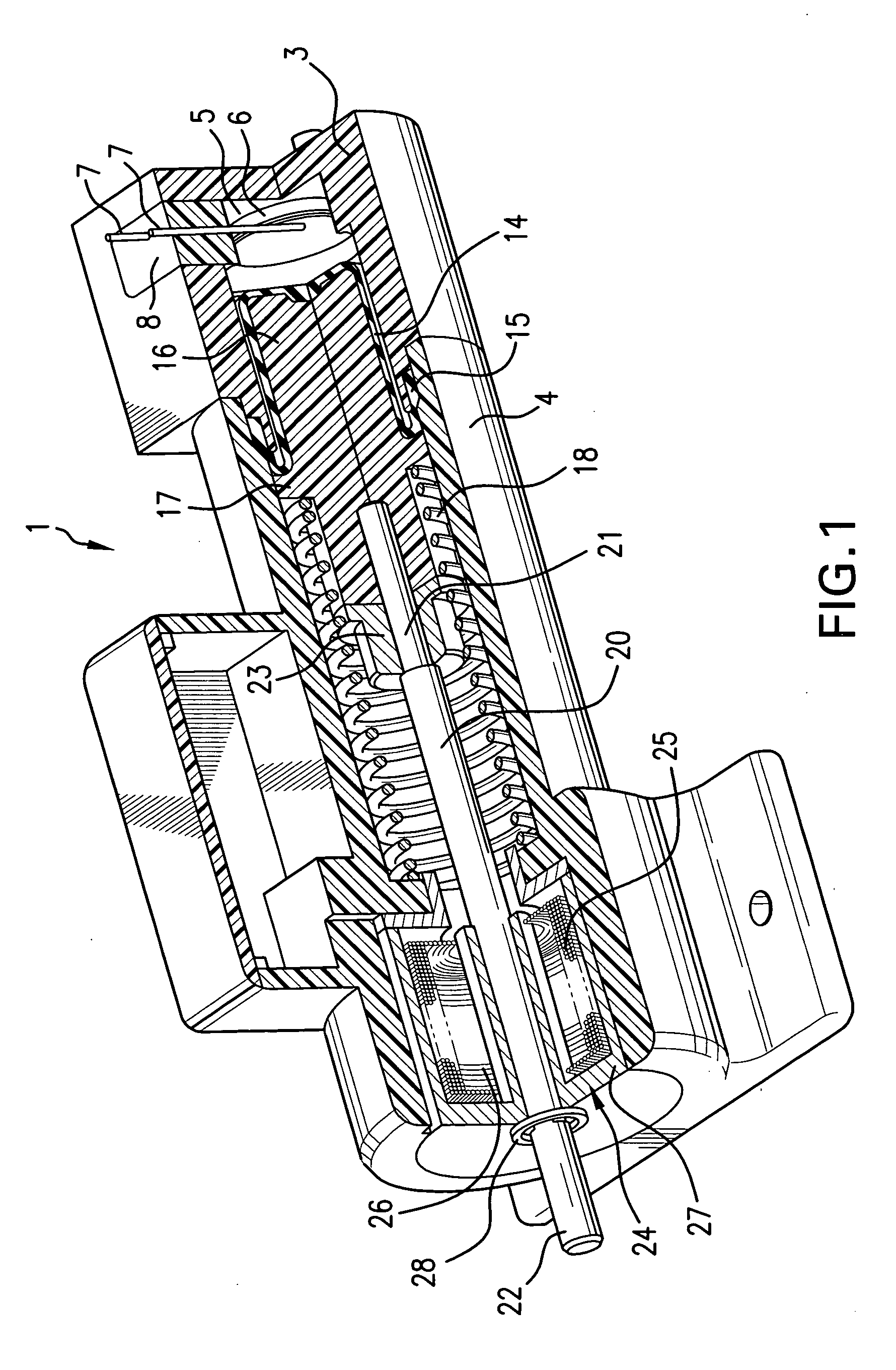
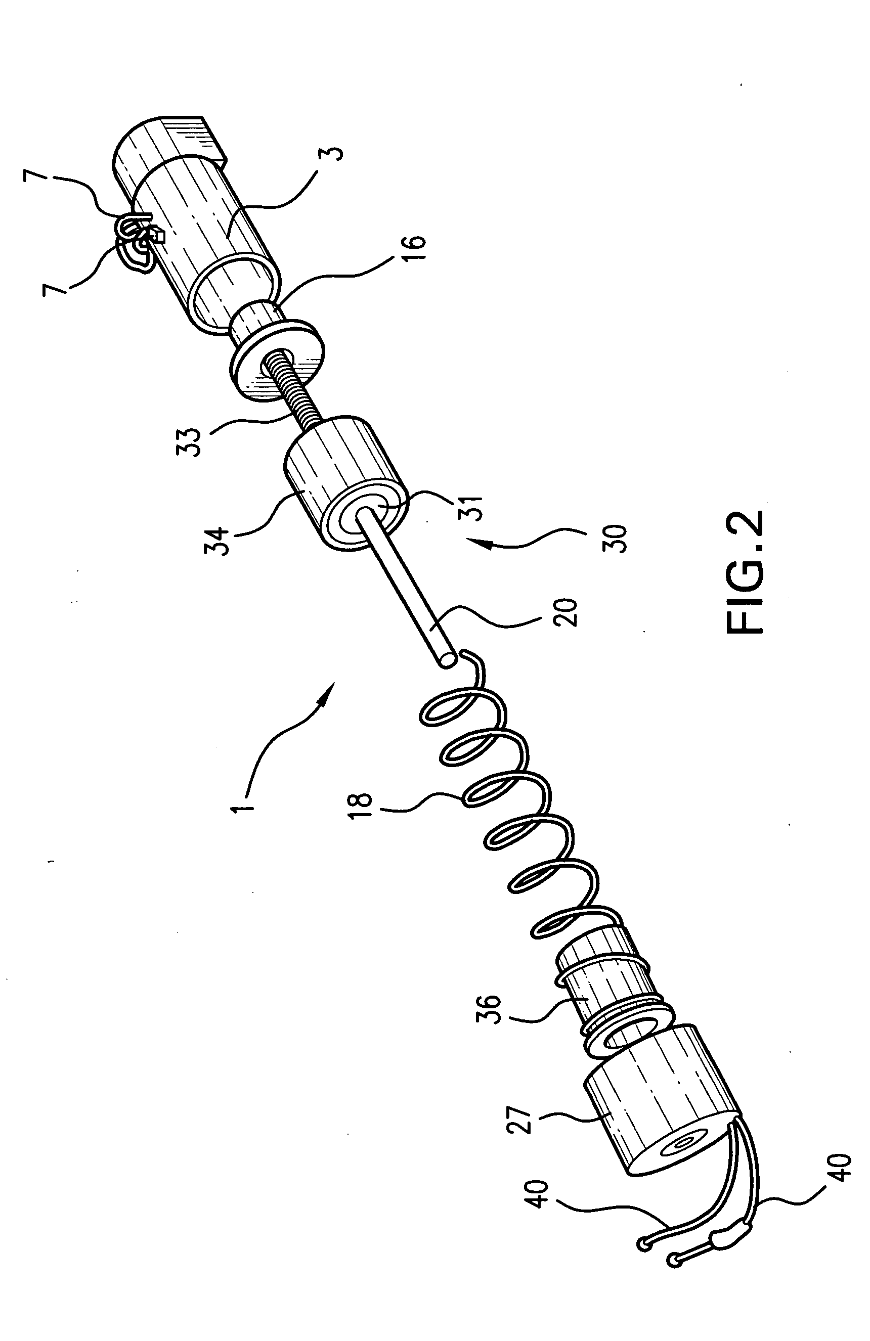
[0017]FIG. 1 shows, in a partially sectioned pictorial view, a first embodiment of a thermo-magnetic actuator 1 according to the invention. The thermo-magnetic actuator 1 includes a housing having a rear or proximal housing part 3, and a distal housing part 4 that are joined together. The housing parts, as illustrated in FIG. 1, are preferably plastic parts that are bonded together, but could be metal. The plastic parts are a material able to withstand the temperature of the working fluid and other elevated temperatures produced by the heater that is described below. The proximal housing part 3 includes a chamber 5 that contains a working fluid, frequently a fluorocarbon. The chamber also houses an electrical heater 6, shown in the form of a disk, with electrical leads 7 that pass through the wall of the distal part of the housing so that an electrical current can be supplied to the heater 6. If the housing is electrically conducting, an electrically insulating material 8 fills an o...


PUM


Abstract

A thermo-magnetic actuator includes a housing; a chamber within the housing; a working fluid changing phase upon heating and located in the chamber; an electrical heater disposed within the chamber for heating the working fluid upon application of electrical power to the electrical heater; a piston rod slidably disposed in the housing and movable between a retracted position, retracted with respect to the housing, and an extended position extending substantially outward of the housing, the piston rod being driven and sliding from the retracted position to the extended position in response to heating of the working fluid by the electrical heater; a spring biasing the piston rod toward the retracted position; an electromagnet disposed at an end of the housing and generating a magnetic field when an electric current is supplied to the electromagnet; and a ferromagnetic target assembly attached to the piston rod, sliding within the housing, and attracted toward the electromagnet, when an electrical current flows through the electromagnet, to maintain the piston rod in the extended position even if electrical power is no longer applied to the heater. Preferably, the position of the piston rod is detected by the actuator and electrical current flow to the electrical heater is terminated when the piston rod is detected at the extended position.

Description

FIELD OF THE INVENTION[0001]The present invention relates to actuators in which linear motion of an object is produced in response to a stimulus, usually electrical power, and reversal of the motion results from withdrawal of the same stimulus or release of an influence preventing reversal of the motion. The invention particularly relates to actuators with reduced power consumption after application of the stimulus and before reversal of the linear motion. The invention further relates to actuators in which a magnetic field provides an influence for preventing reversal of the linear motion after withdrawal of the stimulus and until removal of the magnetic field.BACKGROUND OF THE INVENTION[0002]Actuators producing mechanical movement of an object in response to the application of a stimulus, such as electrical power, are well known. Among the types of actuators that are small and that respond to the application of electrical power to produce a linear motion are electrothermal actuato...

Claims


Application Information

Patent Timeline
Patent Type & Authority Applications(United States)
IPC IPC(8): F03C5/00F03C99/00
CPCH01F7/1638F03G7/06H01F7/121
Inventor SAFRAN, LESDOUGLASS, STEPHEN L.
Owner THERMOTION ACQUISITION
Why Eureka
Try Eureka