Apparatus for kinetic energy storage

a technology of kinetic energy storage and apparatus, which is applied in the direction of mechanical propulsion power, dynamo-electric machines, motors, etc., can solve the problems of low efficiency of prior art apparatus for kinetic energy storage, and achieve the effects of reducing the mass of the flywheel body, reducing the cost of production, and increasing the efficiency of inventive apparatus

Active Publication Date: 2014-05-08
PFEIFFER VACUUM GMBH
View PDF4 Cites 23 Cited by
  • Summary
  • Abstract
  • Description
  • Claims
  • Application Information

AI Technical Summary

Benefits of technology

[0016]According to a still further advantageous embodiment of the invention, it is contemplated that the flywheel body or the housing has pump-active surfaces which are formed parallel to a rotational axis as a screw-type pump stage or as cross-channel pump stage, and pump-active surfaces which are formed transverse to the rotational axis, are formed as a Siegbahn pump stage. Thereby, the efficiency of the inventive apparatus is noticeably increased.
[0017]According to yet another advantageous embodiment of the invention, the flywheel body is formed as one of a rotatable sleeve and a rotatable cylinder. The sleeve or the cylinder is mounted on a hub. The advantage of this embodiment consists in that it is formed of simple and, therefore, inexpensively produced components.
[0018]A still another advantageous embodiment contemplates that the hub is formed as a hub a cross-section of which widens toward the flywheel body. In this embodiment, the mass of the flywheel body, which consist of the hub and a cylinder, noticeably increases, whereby the efficiency is likewise increases.
[0019]A still further embodiment of the invention contemplates that the flywheel body is formed as a rotatable solid cylinder secured directly on the rotor shaft. In this embodiment, the flywheel body has a very big mass, whereby the efficiency is noticeably increased.
[0020]A yet further embodiment of the invention contemplates that the flywheel body is formed of metal and / or fiber-unforced plastic material. When formed of metal, the flywheel body has a very big mass, whereby the energy accumulator is optimized. The advantage of forming the flywheel body of a carbon fiber-reinforced plastic material consists in that that flywheel body can be produced in a simple and cost-effective manner.

Problems solved by technology

The drawback of this apparatus consists in that the efficiency of this prior art apparatus for kinetic energy storage is relatively low because this apparatus operates under atmospheric pressure.

Method used


Image

  • Apparatus for kinetic energy storage
  • Apparatus for kinetic energy storage
  • Apparatus for kinetic energy storage

Examples


Embodiment Construction

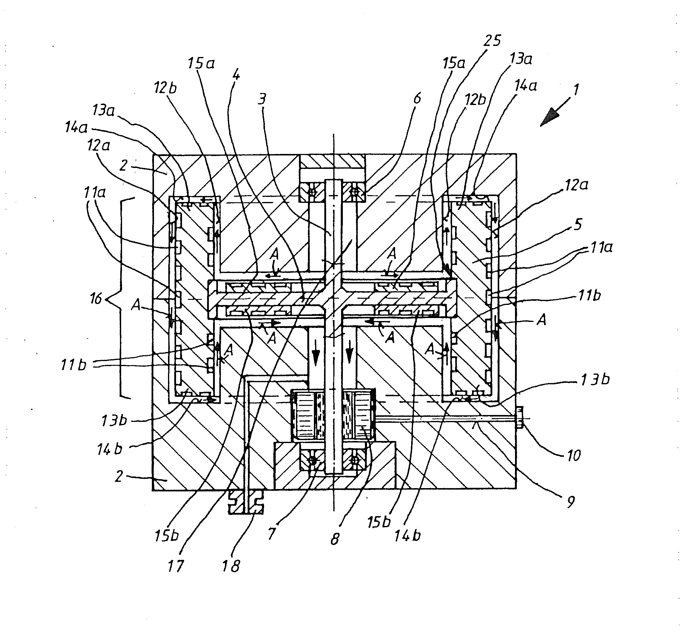
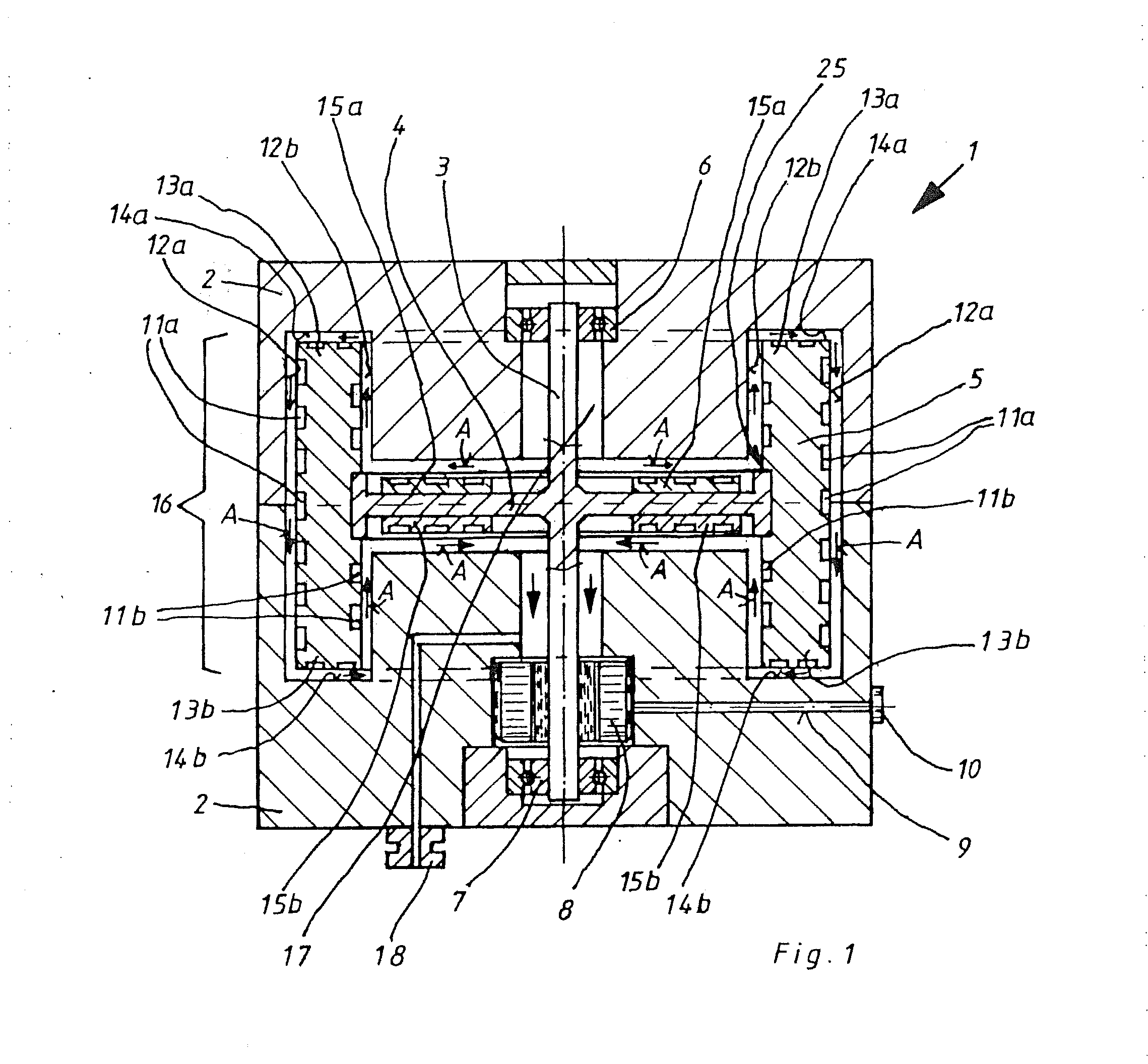
[0033]FIG. 1 shows an apparatus 1 for kinetic energy storage and having a housing 2, a rotor shaft 3 which is secured on a hub 4. A flywheel body 5, which is formed as a hollow cylinder, is also arranged on the hub 4. Bearings 6 and 7 rotatably support the rotor shaft 3. An electrical machine 8 that operates either as a motor or as a generator, has an electrical leadthrough 9 leading to an electrical connection 10.

[0034]The flywheel body 5 has channels 1 la which, together with inner wall 12a of the housing 2, form a screw-type pump stage 16. The screw-type pump stage 16 cooperates with inner walls 12a.

[0035]The view in FIG. 1 shows simply an exemplary embodiment. With a Holweck pump stage, pump-active surfaces are arranged in the housing, and the rotor surfaces are formed smooth. With the screw-type pump stage 16, the pump-active surfaces are provided in the rotor surface, and the inner surfaces of the housing are formed smooth. Usually, with a Siegbahn pump stage, pump-active sur...


PUM


Abstract

An apparatus for kinetic energy storage includes an electrical machine operable at least in one of motor mode and generator mode, and at least one energy recovery system for an intermediate storage of a produced kinetic energy and which converts the kinetic energy into an electrical energy, with, the at least one energy recovery system having at least one flywheel body formed as a rotor, and a stator and with at least one of the rotor and the stator being formed as at least one vacuum pump stage.

Description

BACKGROUND OF THE INVENTION[0001]1. Field of the Invention[0002]The invention relates to an apparatus for kinetic energy storage.[0003]2. Description of the Prior Art[0004]The prior art (DE 102010023531A1) discloses an apparatus for a smart network capacity control by kinetic energy storage.[0005]The apparatus has a flywheel energy accumulator with an electric motor. The drawback of this apparatus consists in that the efficiency of this prior art apparatus for kinetic energy storage is relatively low because this apparatus operates under atmospheric pressure.[0006]The prior at (DE 202011108033U) further discloses an apparatus with at least one energy recovery system for intermediate storage of a produced kinetic energy and which converts the kinetic energy into an electrical energy, wherein the at least one energy recovery system is formed of an electrical machine operable based on a reluctance principle and having a rotor formed as a flywheel body and a stator fixedly connected wit...

Claims


Application Information

Patent Timeline
Patent Type & Authority Applications(United States)
IPC IPC(8): H02K7/02B60L50/30
CPCH02K7/025F03G3/08F04D19/044Y02T10/70
Inventor BREMER, WOLFGANGCONRAD, ARMIN
Owner PFEIFFER VACUUM GMBH
Why Eureka
Try Eureka