Forming a composite structure by filament placement on a tool surface of a tablet

a technology of composite structure and filament, which is applied in the direction of dough shaping, manufacturing tools, food shaping, etc., can solve the problems of increasing cycle times and operating costs of the autoclave portion of the manufacturing process, and increasing the complexity of the mandrel design. , the effect of reducing undesirable and unnecessary costs

Active Publication Date: 2011-08-23
INGERSOLL MACHINE TOOLS
View PDF4 Cites 21 Cited by
  • Summary
  • Abstract
  • Description
  • Claims
  • Application Information

AI Technical Summary

Benefits of technology

[0009]The invention provides a method and apparatus for forming a composite structure with an automatic placement head, through use of a non-rotating tooling tablet having first and second substantially oppositely facing surfaces thereof, joined around the peripheries thereof by a side surface of the tablet, with at least one of the first or second surfaces forming a tool surface of the tablet. In practicing the invention, the automated fiber placement head is utilized for applying layers of pre-impregnated fiber or tape onto the tool surface of the tablet. When application of the fiber or tape onto the tool surface is completed, the tablet, with the pre-impregnated composite material deposited on the tooling surface thereof, is placed into an autoclave for curing of the composite structure. Because the tablet does not rotate, problems encountered in prior automated fiber placement machines, such as undesirably large mass of the tool, long heating and cooling cycle times, complexity of the mandrel design, and undesirable and unnecessary costs are significantly reduced or eliminated through practice of the invention.
[0011]A tool surface on a tooling tablet, according to the invention, may define either an outside mold line, or an inside mold line of the composite structure, with essentially equal efficacy, thus providing significant advantage over prior automated fiber placement machines utilizing rotating mandrels.
[0012]The second side of a tooling tablet, according to the invention, may define a second tool surface, with a method, according to the invention further comprising, placing a second set of pre-impregnated fibers and / or pre-impregnated tape onto the second tool surface with the placement head, to form a second composite structure separate from the first composite structure. The first and second composite parts may be components of a common structure, such as, for example the upper and lower wing skins of an aircraft wing. The tooling tablet may be placed into an autoclave for curing the first and second composite structure simultaneously as a set, thereby potentially facilitating manufacture and inventory control.

Problems solved by technology

The tool that the composite material is laid onto is often quite complex, in that the geometry of the finished part is machined into the tool surface.
Although the use of rotating mandrel tools with automated fiber placement machines generally works well for cylindrical-shaped components, such as fuselage sections, and nose or tail cones in aircraft manufacture, for example, the use of rotating mandrels does present certain problems for designers and manufactures of composite structures.
Because the mandrel must be placed into the autoclave with the composite structure for curing the composite material deposited on the surface of the mandrel, the autoclave is required to heat the mass of the mandrel to a sufficient temperature for curing the part, which greatly increases cycle times and operating cost for the autoclave portion of the manufacturing process.
Also, because the composite materials are wrapped sequentially onto the outer surface of the mandrel, it is not possible to form an outer mold line “OML” surface on the composite structure.
Additional problems are encountered, when attempting to use rotating mandrels for the formation of parts which are not symmetrical about an axis of rotation, thus creating problems and balancing the mandrel, or parts which have a cross section which is flat, complex, or otherwise constricted in such a manner that it is very difficult to remove the mandrel from the part, after the autoclave cycle.
Although rotating mandrels have sometimes been used, in the past, to form such parts, it has been necessary to provide means and manufacturing processes for essentially cutting the desired planar-shaped part away from the remainder of the wound structure, following the autoclave cycle, resulting in undesirable manufacturing cost and waste of material.

Method used


Image

  • Forming a composite structure by filament placement on a tool surface of a tablet
  • Forming a composite structure by filament placement on a tool surface of a tablet
  • Forming a composite structure by filament placement on a tool surface of a tablet

Examples


Embodiment Construction

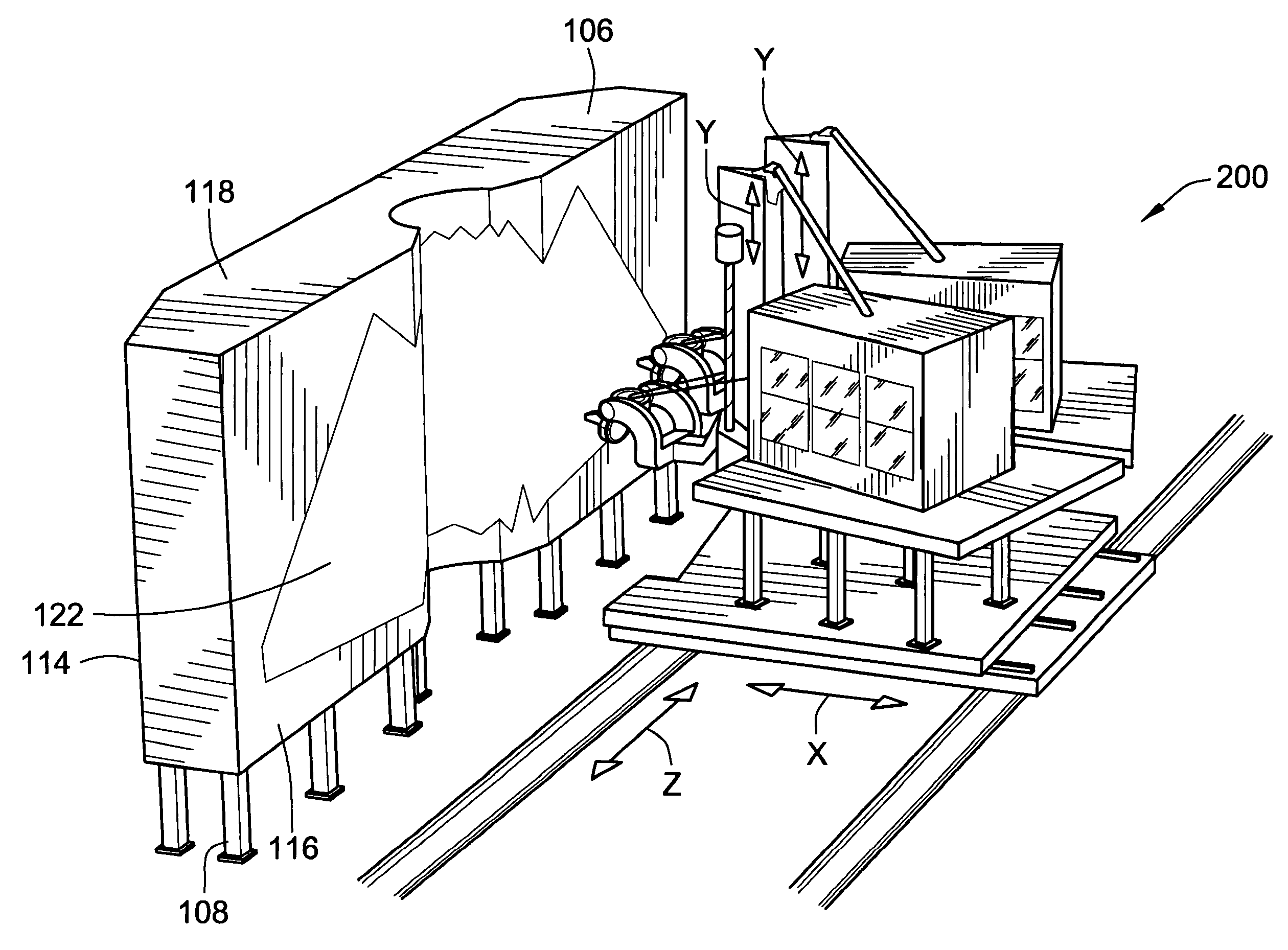
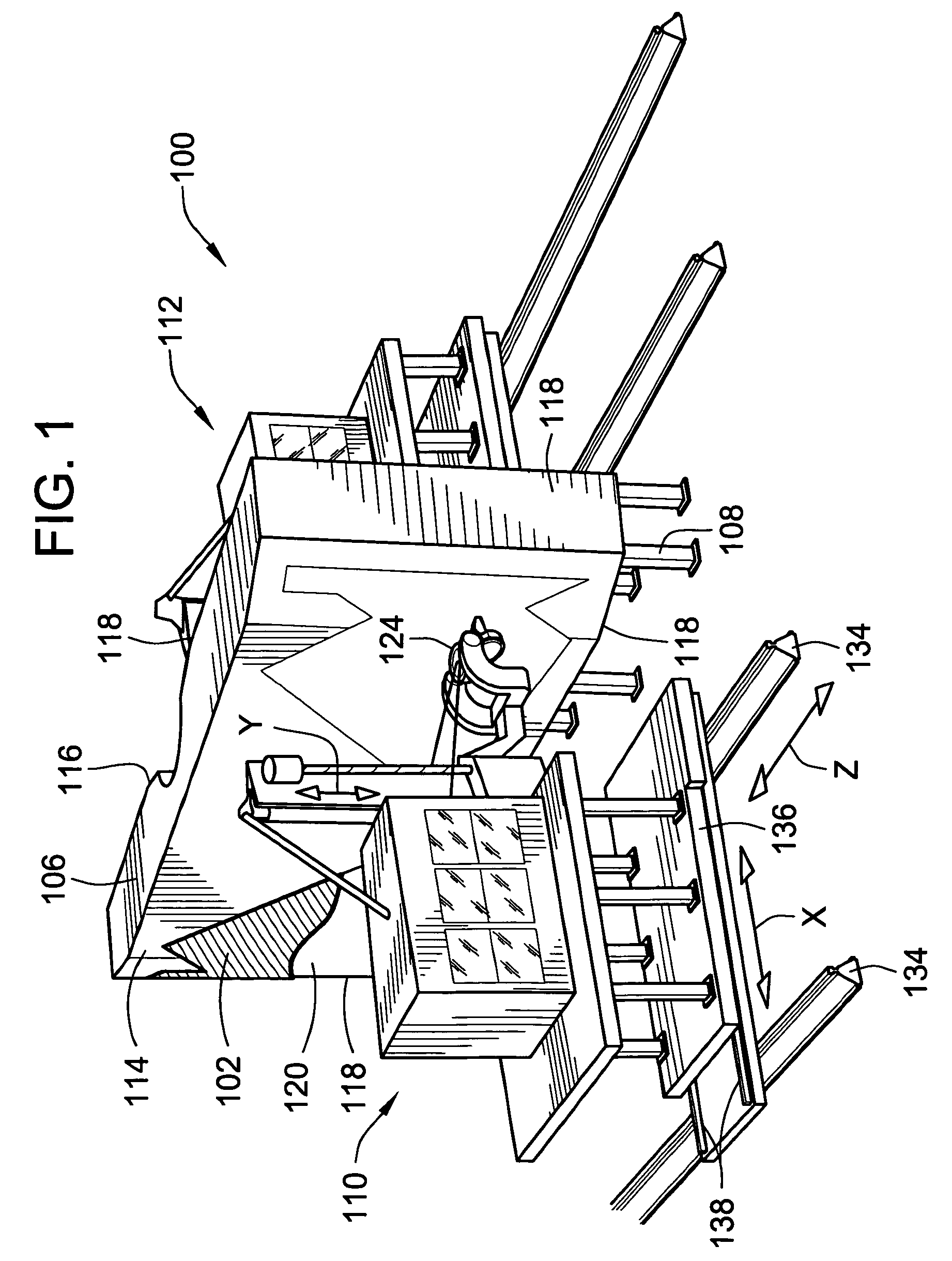
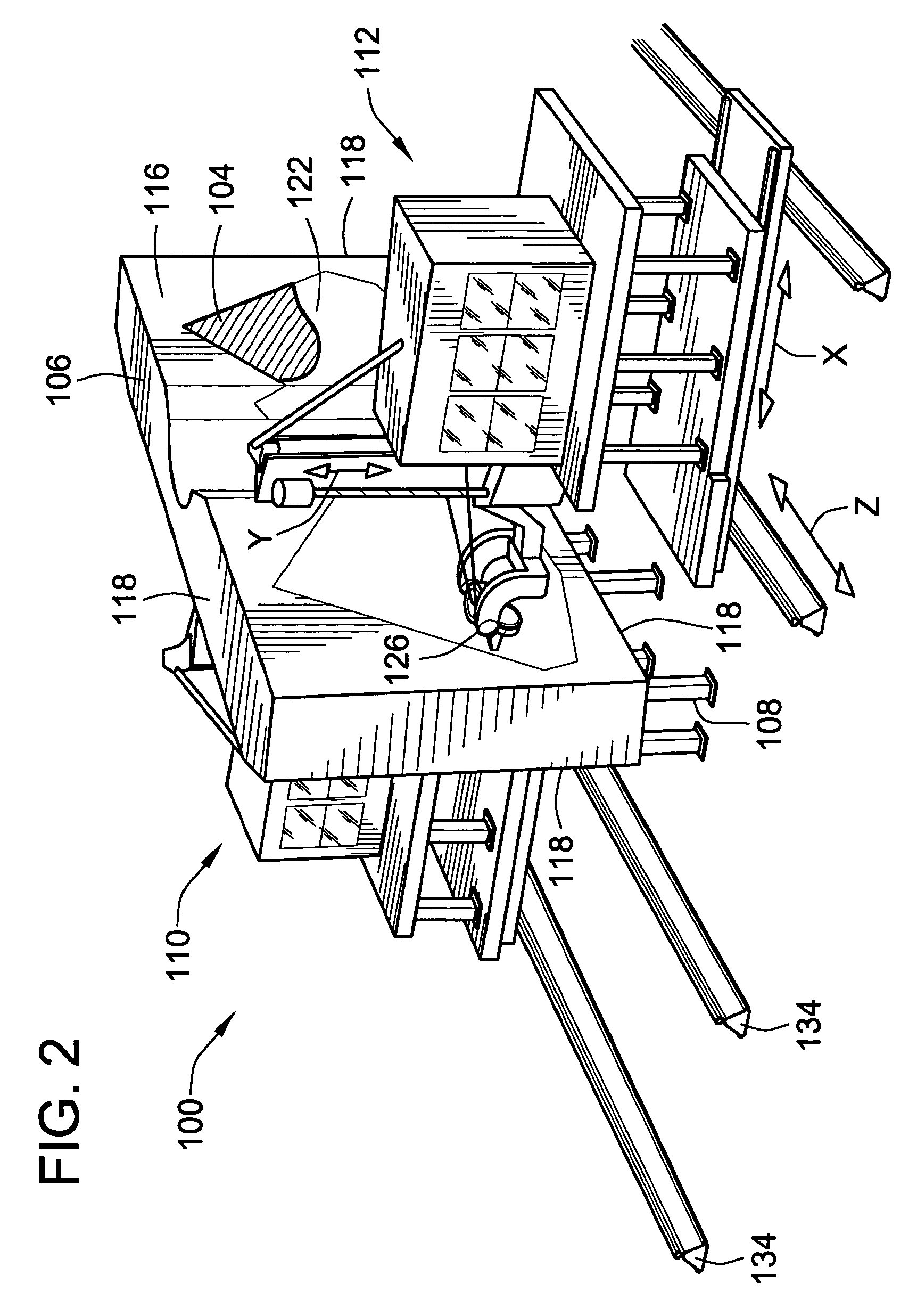
[0028]FIGS. 1 and 2 show a first exemplary embodiment of the invention in the form of an apparatus 100 for simultaneously forming the upper and lower skin 102, 104 for an aircraft wing. The apparatus 100 includes a tooling tablet 106 mounted on an indexing tablet mounting structure 108 between a first and a second fiber placement machine 110, 112.

[0029]The tooling tablet 106 includes first and second substantially oppositely facing surfaces 114, 116 thereof, joined around their peripheries by a side surface 18 of the tablet 106. The first and second surfaces 114, 116 of the tooling tablet 106 of the exemplary embodiment, respectively form first and second tool surfaces 120, 122 of the tablet 106. The first and second tool surfaces 120, 122 are each adapted for receiving pre-impregnated and / or pre-impregnated tape from automated placement heads 124, 126, of the first and second fiber placement machines 110, 112 respectively, for formation of the upper and lower wing skins 102, 104 re...


PUM

PropertyMeasurementUnit
structureaaaaaaaaaa
angleaaaaaaaaaa
temperatureaaaaaaaaaa

Abstract

A method and apparatus are provided for forming a composite structure with an automatic placement head, through the use of a non-rotating tooling tablet having first and second substantially oppositely facing surfaces thereof, joined around the peripheries thereof by a side surface of the tablet, with at least one of the first or second surfaces forming a tool surface of the tablet. Layers of pre-impregnated fiber or tape are applied to the tool surface of the tablet by the automated fiber placement head.

Description

CROSS-REFERENCE TO RELATED PATENT APPLICATIONS[0001]This patent application claims the benefit of U.S. Provisional patent application No. 60 / 564,154, filed Apr. 21, 2004, the teachings and disclosure of which are hereby incorporated in their entireties by reference thereto.FIELD OF THE INVENTION[0002]This invention relates to the forming of composite structures with automated fiber placement machines, and more particularly to fabrication of structural components which are not amenable to being formed on a rotating mandrel.BACKGROUND OF THE INVENTION[0003]Automated fiber placement machines are widely used to manufacture parts, components and structures from composite materials. The materials used in automated fiber placement are typically composed of longitudinal fibers and resin consolidated into tapes, or thin strips commonly known as “tows.” Individual tapes or tows are manipulated by the fiber placement machine to form a band of material that is deposited “laid” onto a tool. Part...

Claims


Application Information

Patent Timeline
Patent Type & Authority Patents(United States)
IPC IPC(8): D01D7/00B29C70/30B29C70/38
CPCB29C70/382B29C70/386B29C70/384B29C70/388
Inventor OLDANI, TINOJARVI, DANIEL
Owner INGERSOLL MACHINE TOOLS
Why Eureka
Try Eureka