Rotary tool box

Inactive Publication Date: 2014-05-20
CHEN CHAO MING
View PDF49 Cites 11 Cited by
  • Summary
  • Abstract
  • Description
  • Claims
  • Application Information

AI Technical Summary

Benefits of technology

[0006]Secondary object of the present invention is to provide a rotary tool box which is capable of removing a tool from the rotary tool box and placing the tool into the rotary tool box easily

Problems solved by technology

Unfortunately, the tool holder 10 cannot provide a theft-proof function, so the plurality

Method used


Image

  • Rotary tool box
  • Rotary tool box
  • Rotary tool box

Examples


Example

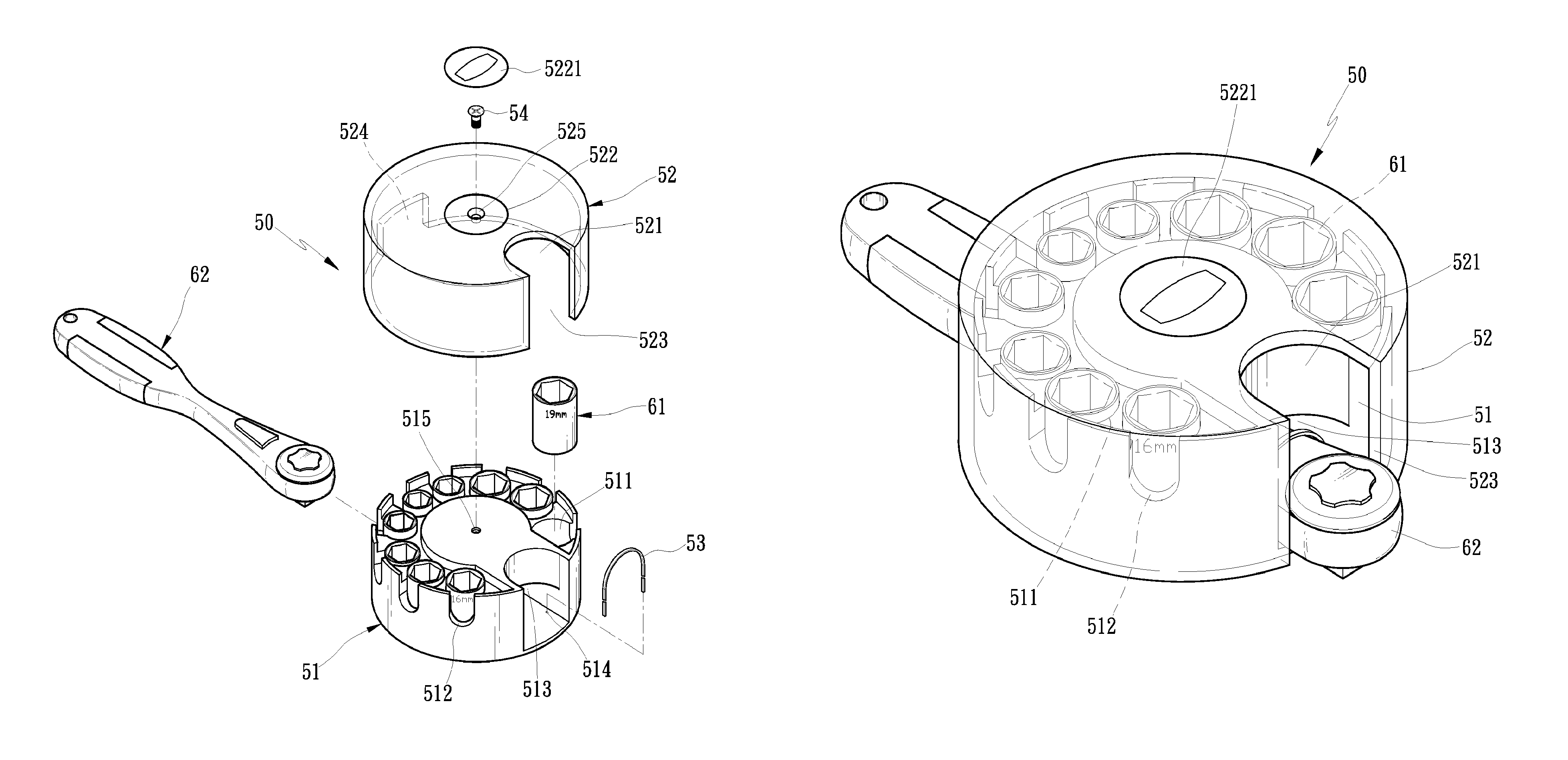
[0029]FIG. 3 is a perspective view showing the exploded components of a rotary tool box according to a first embodiment of the present invention. FIG. 4 is a perspective view showing the assembly of the rotary tool box according to the first embodiment of the present invention. The rotary tool box 50 comprises a base 51 and a covering member 52. The base 51 includes a plurality of receiving portions for receiving plural tools (such as sleeves, bits, and the like). In this embodiment, the base 51 is circular and each receiving portion is a groove 511 defined on a top surface thereof, such that a plurality of grooves 511 of the base 51 receive plural sleeves 61 with different sizes. Also, the base 51 includes a plurality of recesses 512 formed around an outer surface thereof and communicating with the plurality of grooves 511. In this embodiment, the plurality of recesses 512 pass through the outer surface of the base 51 and the plurality of grooves 511 so that the plural sleeves 61 i...


PUM


Abstract

A rotary tool box contains a base including a plurality of receiving portions for receiving plural tools and at least one accommodation room for holding at least one driving tool, at least one end of which extends out of the at least one accommodation room; a covering member covered on the base and including at least one orifice defined on a top surface thereof so as to take or place the at least one driving tool, the covering member also including at least one slot formed on an outer surface thereof so that the at least one end of the at least one driving tool extends out of the accommodation room and is engaged.

Description

FIELD OF THE INVENTION[0001]The present invention relates to a rotary tool box which has a theft proof and display function.BACKGROUND OF THE INVENTION[0002]FIG. 1 shows a conventional tool holder for holding sleeves. The tool holder 10 includes a base 11 and a plurality of holding mounts 12. The base 11 is elongated and has two sliding rails 111 fixed on two sides thereof. Each holding mount 12 has two recesses 121 defined on two sides of a bottom end thereof so as to correspond to the two sliding rails 111, such that the each holding mount 12 is slidably mounted on the base 11. Also, the each holding mount 12 has a quadrilateral retaining portion 122 disposed on a top end thereof so as to insert a fitting segment 21 of a socket 20, wherein the fitting segment 21 is a quadrilateral hole, such that a plurality of sleeves 20 with different sizes are placed on the tool holder 10. Unfortunately, the tool holder 10 cannot provide a theft-proof function, so the plurality of sleeves 20 ar...

Claims


Application Information

Patent Timeline
IPC IPC(8): A45C11/26B25H3/02B65D83/00B65D73/00B25H3/00B65D85/28
CPCB25H3/003B25H3/022
Inventor CHEN, CHAO-MING
Owner CHEN CHAO MING
Why Eureka
Try Eureka