Rim space seal system for use with internal floating roof

a technology for rim space seals and floating roofs, which is applied in the direction of engine seals, packaging, machines/engines, etc., can solve the problems of endangering human inspectors, the rim seal does not have any protection from the reversal of movement flexure, etc., to prevent unwanted leakage, prevent abrasion or puncture, and maintain integrity

Active Publication Date: 2014-05-20
ROSENKRANTZ DAVID JON
View PDF12 Cites 1 Cited by
  • Summary
  • Abstract
  • Description
  • Claims
  • Application Information

AI Technical Summary

Benefits of technology

[0011]The present invention is a rim seal system extending between the outer periphery of an internal floating roof and the bulk liquid tank wall. The rim seal system includes a laterally deployed first resilient or flexible sealing member and a second laterally deployed rigid sealing member interposed between the distal end of the first sealing member and the tank wall where the rigid seal member provides protection from abrasion of the resilient or flexible seal member by frictional contact with the tank wall. The rigid sealing member is held in proximal contact with the storage tank wall by an outwardly expanding hanger assembly mounted above the rim seal system.
[0012]The rim seal system is intended for use with an internal floating roof for a bulk liquid storage tank to prevent unwanted leakage and evaporation of the stored liquid. The rim seal system includes a primary sealing member mounted to and deployed laterally outward from the perimeter wall of the internal floating roof. The primary sealing member has sufficient length to span the rim space distance between the perimeter wall of the internal floating roof and the storage tank wall. The primary sealing member also has the capacity to resiliently compress when the rim space contracts due to lateral movement of the internal floating roof.
[0013]The rim seal system also includes a secondary rigid sealing member mounted to and deployed laterally outward from the perimeter wall of the internal floating roof. The secondary sealing member is interposed between the primary sealing member and the storage tank wall and is maintained in proximal contact with the storage tank wall by an outwardly expanding hanger assembly. The hanger assembly includes a plurality of tension joints with interspersed extension plates for urging the hanger assembly to its maximum length, thus causing the attached secondary rigid sealing member to remain in contact with the storage tank wall at all times. The combination of the two sealing members provides the protection against leakage and evaporation of the stored liquid by operating together to fill the rim space distance between the perimeter wall of the floating roof and the storage tank wall. The secondary rigid sealing member by its interposition between the primary sealing member and the storage tank wall also provides abrasion protection for the primary sealing member as the internal floating roof changes vertical position due to volumetric changes in the stored liquid within the storage tank.

Problems solved by technology

However, the wiper seal does not have any protection from the reversal of movement flexure or from the frictional contact with the metal tank wall.
The problems with both sealing systems was that in order to inspect the primary seal one was required to remove the secondary seal exposing the vapor collection space to the atmosphere and potentially endangering the human inspector.

Method used


Image

  • Rim space seal system for use with internal floating roof
  • Rim space seal system for use with internal floating roof
  • Rim space seal system for use with internal floating roof

Examples


first embodiment

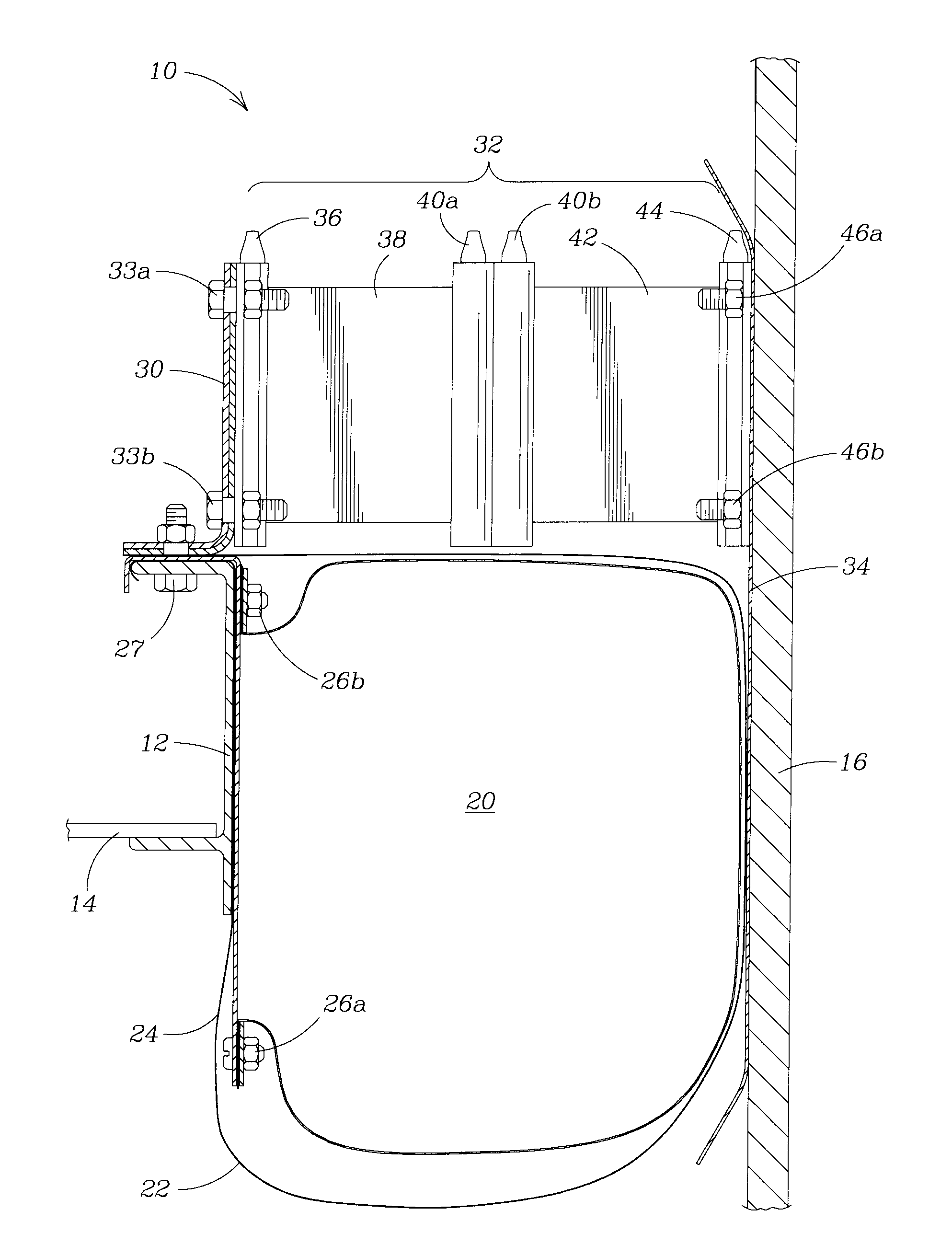
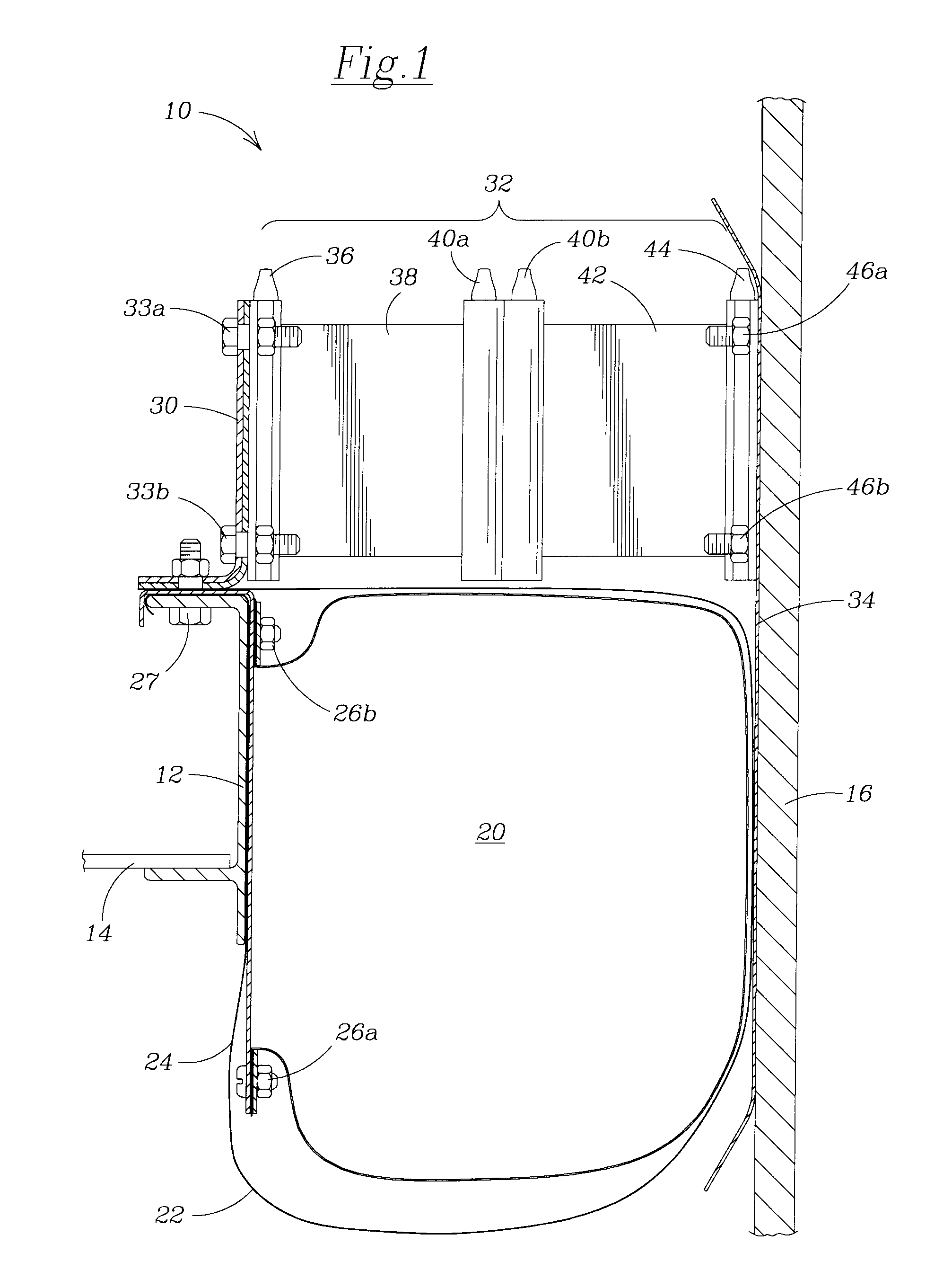
[0022]Referring now to the drawings in detail, where like numerals refer to like parts or elements, there is shown in FIG. 1 a peripherally mounted floating roof seal 10 of the present invention. The seal is mounted to the outer perimeter structure of an internal floating roof within a storage tank. The perimeter structure of the floating roof shown in FIG. 1 includes an outer sidewall 12 of an open top panel system having a bottom plate 14 extending inward into the space defined by the other sidewalls of the panel system. The floating roof structure is set off from the inner tank wall 16 creating an annular or rim space in which the floating roof can move in the horizontal plane as its floats on the surface of the stored liquid. In the annular or rim space a seal is deployed to reduce as much as possible the evaporation of the stored liquid into the internal tank atmosphere. In this embodiment the seal is depicted as a liquid-mounted seal 20 with a solid foam core disposed within a...

second embodiment

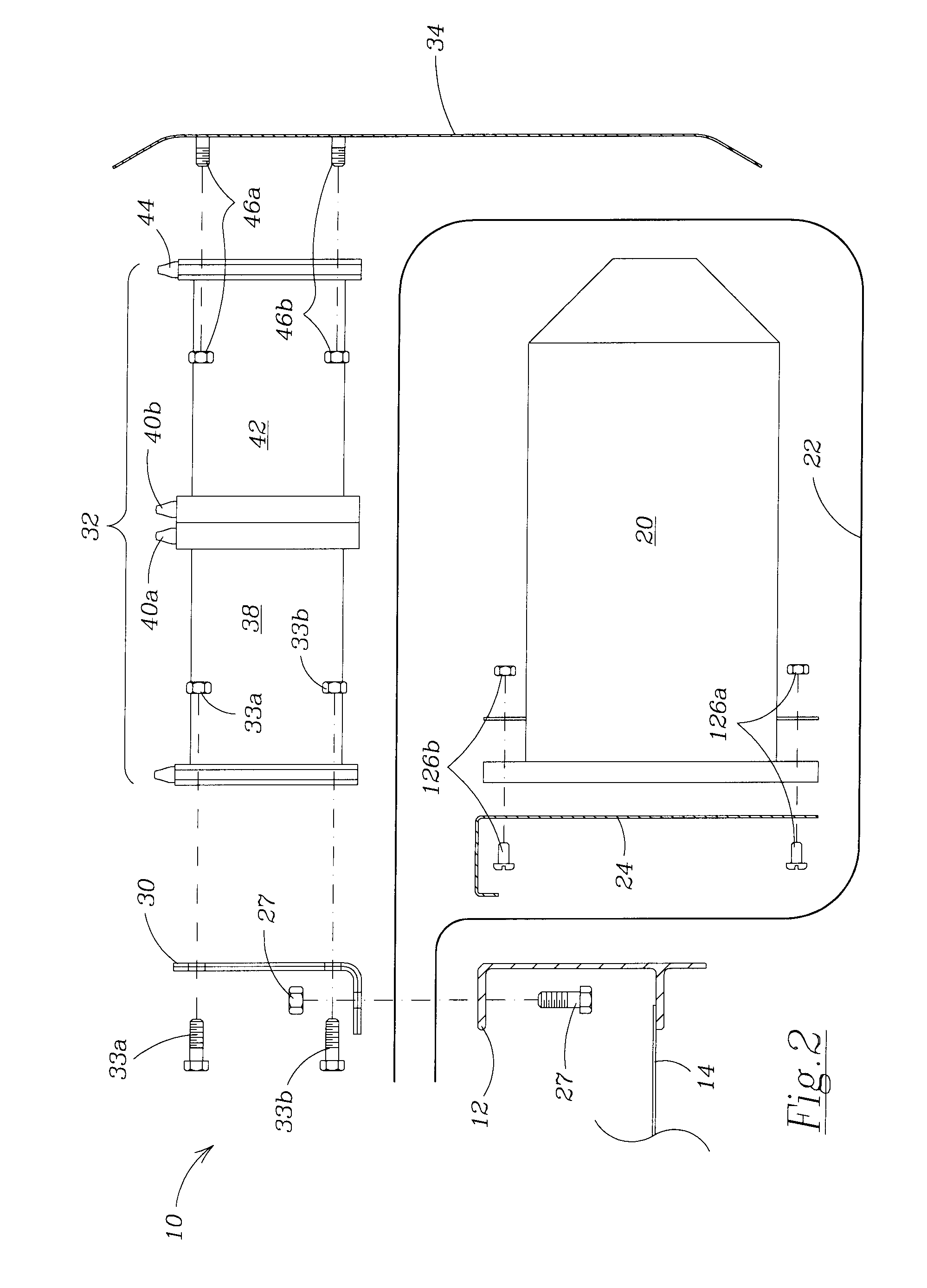
[0030]In FIG. 4 the rim seal system 110 of the present invention is depicted with a flexible membrane type seal as the primary seal and a wiper type seal positioned above as the secondary seal. In this embodiment, the rim seal system 110 is comprised of a flexible membrane seal 120 mounted between the outer sidewall 12 of the floating roof and the protective shoe 34. A partial perimeter section of the floating roof is depicted as the outer perimeter sidewall 12 and bottom plate 14 creating one of a plurality of open top panel systems comprising the floating roof. The flexible membrane seal 120 is sandwiched between the upper flange of the outer sidewall 12 and the bottom foot of the extension plate 130 using fastener 127. At its other end, the flexible membrane seal 120 is attached along the mid-portion of the protective shoe 34 by mounting plate 35 and fasteners 37. The extension plate 130 is a reinforced plate extending upward from the top of the outer sidewall 12 and is used to m...


PUM


Abstract

A rim seal system between the outer periphery of an internal floating roof and the bulk liquid tank wall including a laterally deployed first resilient or flexible seal member and a second laterally deployed rigid seal member interposed between the distal end of the first seal member and the tank wall where the rigid seal member provides protection from abrasion of the resilient or flexible seal member by frictional contact with the tank wall. An outwardly expanding hanger assembly mounted above the seal system maintains the rigid seal member in contact with the tank wall.

Description

BACKGROUND OF THE INVENTION[0001]The present invention relates to sealing the space between the internal floating roof and the inner tank wall of a storage tank for volatile or hazardous liquids. The present invention provides a means for protecting the various seal mechanisms utilized with internal floating roofs and extending the life span for those sealing mechanisms.[0002]Bulk fluids, such as petroleum, other fuel products and by-products, and chemicals are often stored in large cylindrical tanks. These tanks are commonly designed with internal floating roofs or bulk fluid covers to minimize product losses to the atmosphere. A critical part of the internal floating roof is the annular or rim space between the perimeter of the internal floating roof and the inner wall of the storage tank. For an average floating roof, approximately one-third of the evaporation loss of the bulk fluid can be attributed to those vapors that escape past the rim seal.[0003]Three types of rim seals are...

Claims


Application Information

Patent Timeline
Patent Type & Authority Patents(United States)
IPC IPC(8): F16J15/34B65D88/46
CPCB65D88/46F16J15/3436
Inventor ROSENKRANTZ, DAVID, JON
Owner ROSENKRANTZ DAVID JON
Why Eureka
Try Eureka