
Grinder container

a technology for grinders and containers, applied in the field of grinder containers, can solve the problems of unfavorable coffee powder diversion in subsequent operations, gap between grinder containers and coffee grinders, and undesired diversion of coffee powder outside the container, and achieve the effect of large dimensional tolerances

Active Publication Date: 2014-05-20
PI-DESIGN AG
View PDF5 Cites 0 Cited by
  • Summary
  • Abstract
  • Description
  • Claims
  • Application Information

AI Technical Summary

Benefits of technology

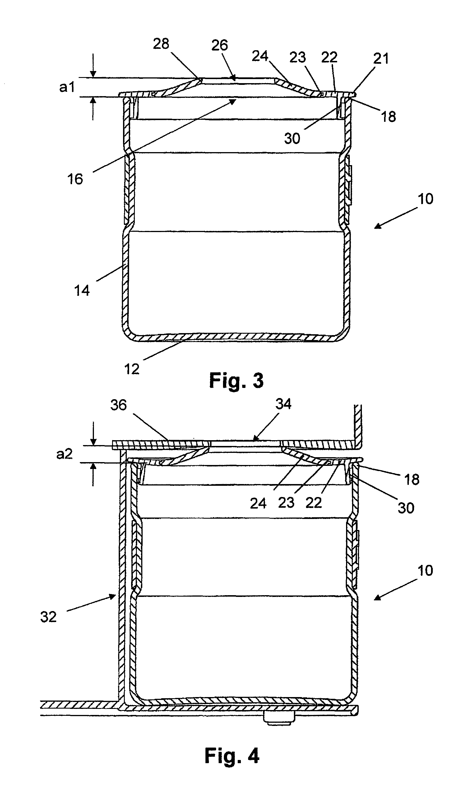
[0005]It is an object of the present invention to create a lid which is suitable for a grinder container of the type mentioned in the introduction, can compensate for relatively large dimensional tolerances in respect of the height of grinder containers and—once inserted in a coffee grinder—ensures a sealed connection between the coffee grinder and lid in the region of the introduction opening in the lid.
[0008]For better sealing between the lid and grinder container, a circumferential sealing lip, which is directed toward the inside of the wall of the grinder container, can project from the free end of the circumferential web.

Problems solved by technology

It is the case with many conventional coffee grinders having a grinder container made of plastics material that the coffee powder is charged electrostatically, which often results in the undesired diversion of adhering coffee powder in subsequent operations and, as a consequence, in contaminations.
However, grinder containers made of glass have a relatively large dimensional tolerance in respect of height, and therefore a gap has to be expected between the grinder container and coffee grinder.
Coffee powder can escape out of this gap, which, in turn, results in the undesired diversion of coffee powder outside the container.

Method used


Image

  • Grinder container
  • Grinder container
  • Grinder container

Examples


Embodiment Construction

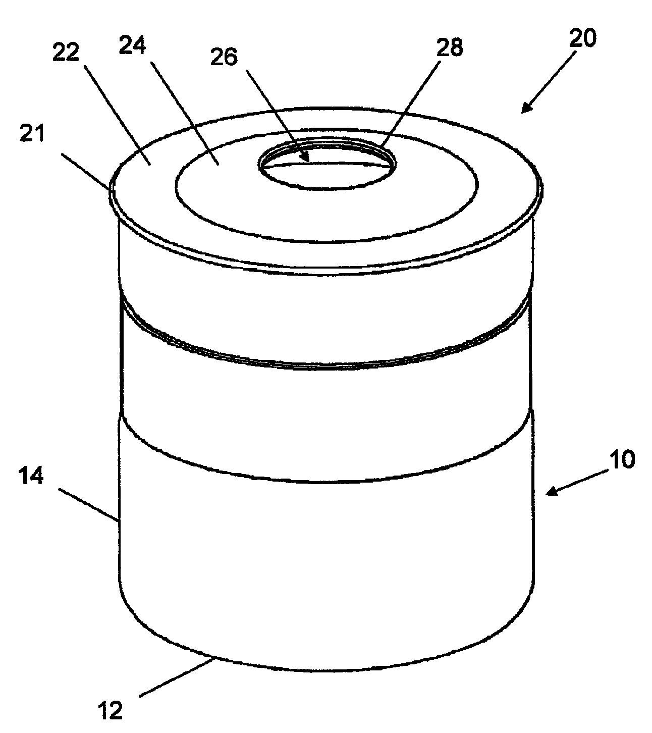
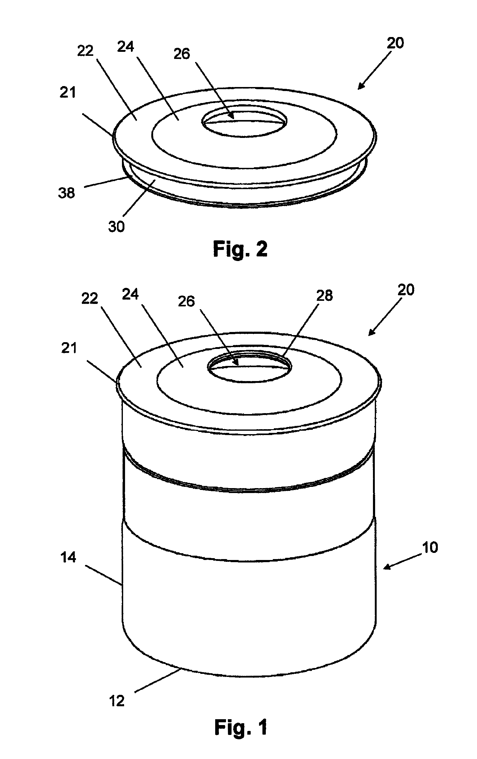
[0020]A grinder container 10, which is illustrated in FIGS. 1 to 3, comprises a base 12 and a substantially cylindrical container wall 14 which projects up from the base 12 and has an opening rim 18 terminating the container wall 14 and bounding a container opening 16.

[0021]A lid 20, which is placed in position on the grinder container 10, is made in two parts and comprises a central lid part 24, with a central introduction opening 26 bounded by an opening rim 28, and a lid-rim part 22, which follows the central lid part 24, is connected thereto via a possibly adhesively bonded groove / tongue connection 23, rests on the opening rim 18 of the container wall 14 by way of a peripheral lid rim 21 and projects laterally beyond this container wall to a slight extent. At a distance from the peripheral lid rim 21, a circumferential web 30 projects substantially vertically inward from the lid-rim part 22 and is located opposite the cylindrical wall 14 of the grinder container 10, at a short d...


PUM


Abstract

A grinder container (10) to be inserted in a coffee grinder comprises a lid (20) having a center inlet hole (26). The lid (20) rests on an opening rim (18) of the grinder container (10) with a peripheral lid rim (21). A peripheral web (30) projects into the interior of the grinder container (10) at a distance to the peripheral lid rim (21) and is opposite an inner wall (X) of the grinder container (10). In order to level out any dimensional tolerances regarding the height of grinder containers, the lid (20) consists of a deformation-resistant center lid part (24) which is produced of a rigid plastic material and comprises the center inlet hole (26) and of an elastically deformable lid part (22) which is produced of a soft rubber material, said lid part being connected to the center lid part (24) and comprising the peripheral web (30).

Description

CROSS REFERENCE TO RELATED APPLICATIONS[0001]This application is a National Stage of International Application No. PCT / CH2010 / 000038 filed Feb. 11, 2010, claiming priority based on Swiss Patent Application No. 01250 / 09, filed Aug. 12, 2009, the contents of all of which are incorporated herein by reference in their entirety.TECHNICAL FIELD[0002]The present invention relates to a grinder container for insertion into a coffee grinder, having a lid which has a central introduction opening, rests on an opening rim of the grinder container by way of a peripheral lid rim and from which, at a distance from the peripheral lid rim, a circumferential web projects into the interior of the grinder container and is located opposite the inside of a wall of the grinder container.PRIOR ART[0003]It is the case with many conventional coffee grinders having a grinder container made of plastics material that the coffee powder is charged electrostatically, which often results in the undesired diversion o...

Claims


Application Information

Patent Timeline
Patent Type & Authority Patents(United States)
IPC IPC(8): B65D43/00B65D43/04B65D43/08B65D43/02
CPCA47J47/06
Inventor BODUM, JORGEN
Owner PI-DESIGN AG
Learn More