
Three roll mill

a three-roll mill and rolling mill technology, applied in the field of grinding mills, can solve the problems of not being able to easily remove individual rolls, requiring a number of different tools, and not being able to easily remove rolls,

Inactive Publication Date: 2014-05-20
SMITH JEFFREY P
View PDF13 Cites 5 Cited by
  • Summary
  • Abstract
  • Description
  • Claims
  • Application Information

AI Technical Summary

Benefits of technology

Enables rapid and tool-free removal of rolls for cleaning, improving maintenance efficiency and reducing the complexity of the disassembly process while maintaining precise control over roll speeds and gap adjustments.

Problems solved by technology

However it is still not easy to remove the individual rolls.
None offers easy removal of rolls.
From the foregoing it will be apparent that removal of the rolls for cleaning requires a number of different tools and is very time-consuming.
Indeed, it is an operation that many users would rather not undertake at all.

Method used


Image

  • Three roll mill
  • Three roll mill
  • Three roll mill

Examples


Embodiment Construction

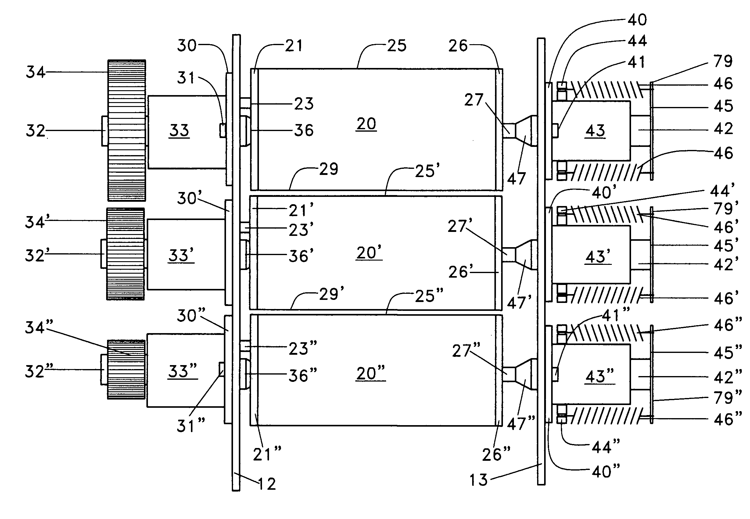
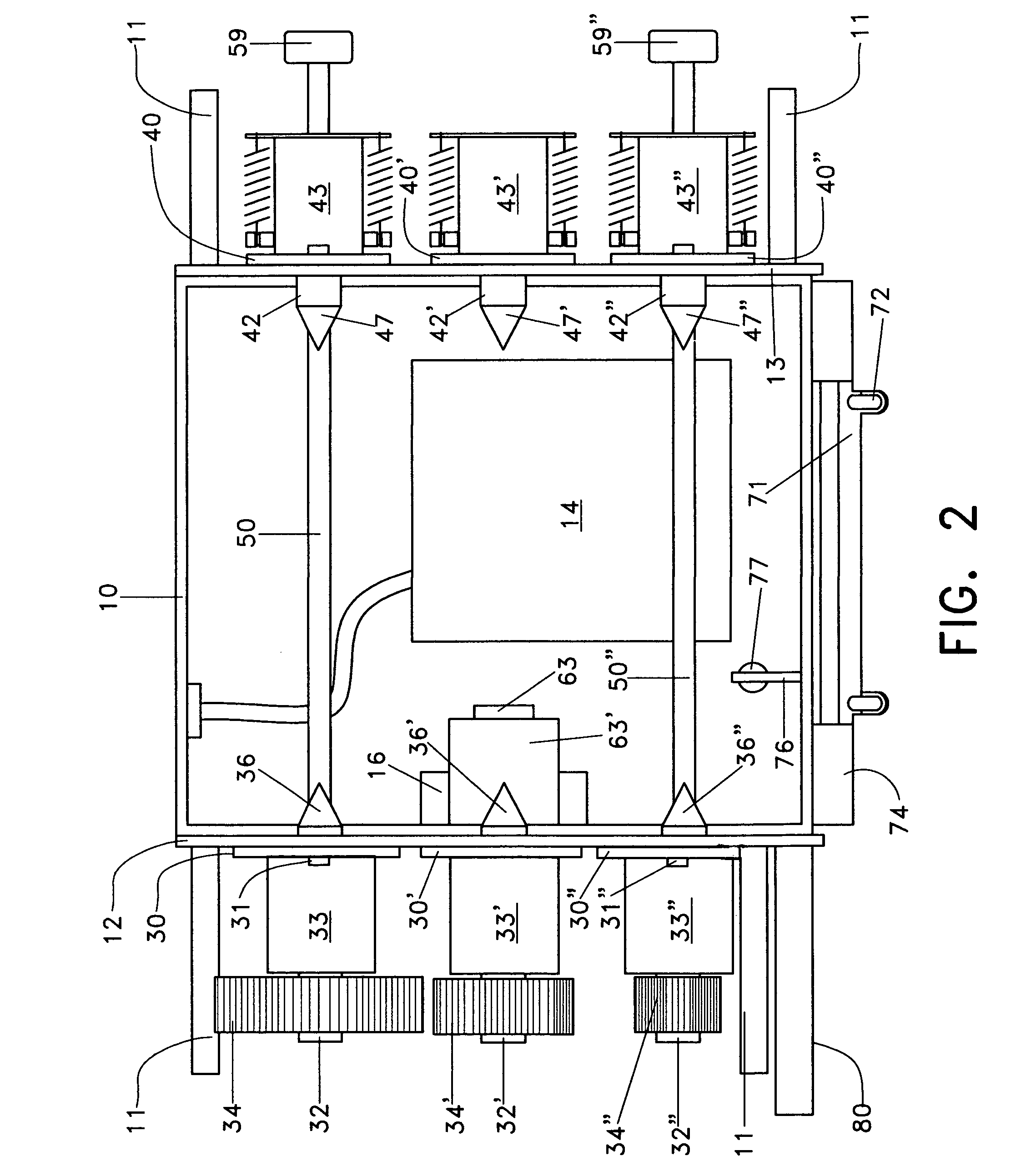
[0022]Since the mounting arrangement for the rolls is substantially identical, components associated with respective rolls will utilize the same reference numerals. Those associated with the feed roll will be unprimed, whereas those associated with the center roll will have a single prime, and those associated with the apron roll will have a double prime.

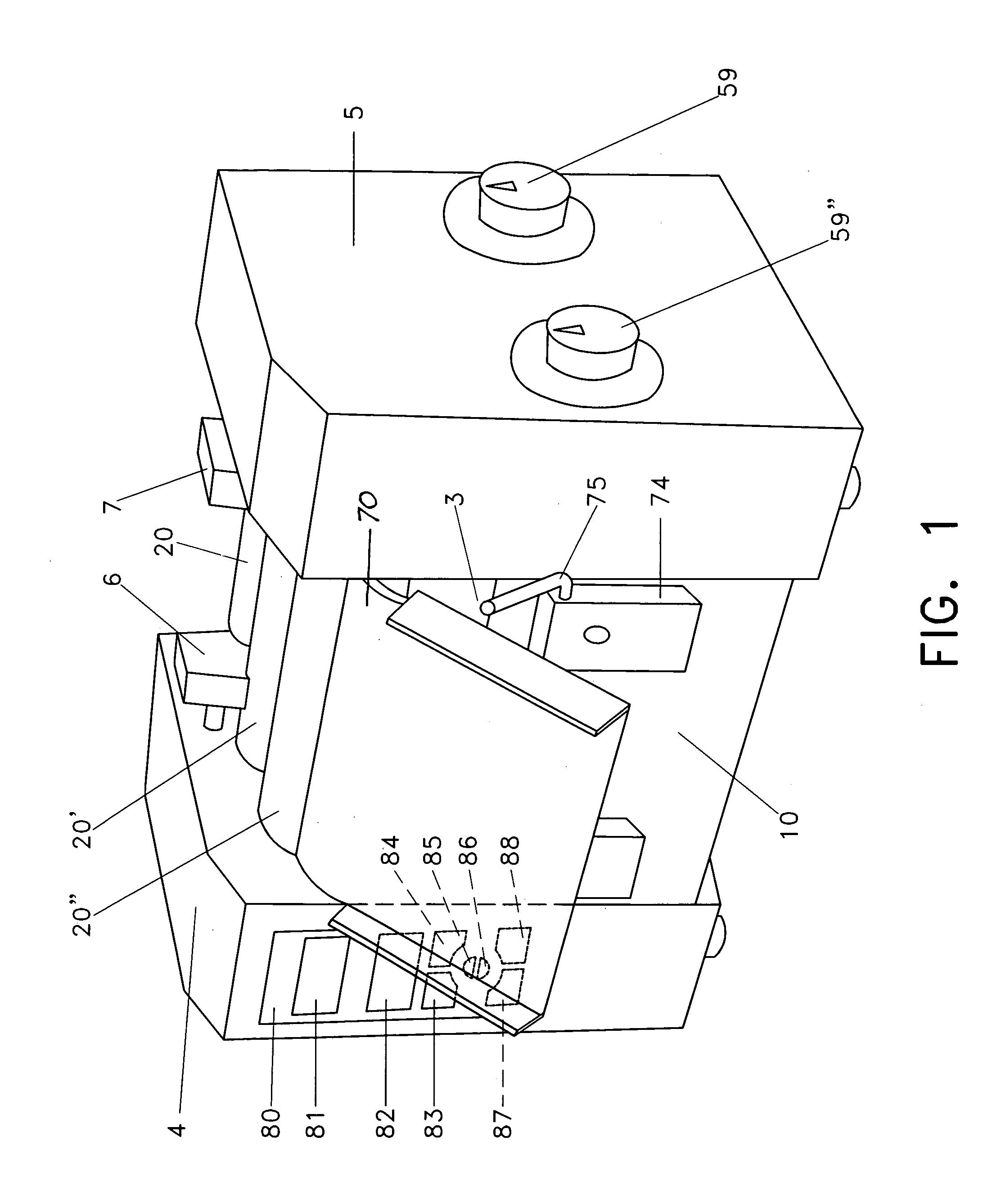
[0023]FIG. 1 shows the three roll mill with the left side cover 4, right side cover 5 and scraper 70 in place on box frame 10. The feed roll 20, center roll 20′, and apron roll 20″ are exposed as in other three roll mills. A pair of spring-loaded guide blocks 6, 7 extend closely into the nip between the feed and center rolls to prevent the escape of material from the ends of the rolls. These are well known and will not be shown again. A platform 3 catches any material that falls off the rolls, and can be easily removed for cleaning. Knobs 59, 59″ are used to control the gaps between rolls, as will be described. Finished ointment is ...


PUM


Abstract

A three roll mill having a feed roll, a center roll, and an apron roll with that are driven so that their cylindrical surfaces move in the same direction but different speeds in each nip. One end of each roll is engaged by a drive shaft at a first side of the mill, whereas the other end of each roll rotates freely at a second side of the mill. Each roll can be removed individually and without tools by moving the roll away from the first side against a spring force in the second side. This disengages the roll from its drive shaft, whereupon it can be lifted out of the mill.

Description

FIELD OF THE INVENTION[0001]The invention relates to a grinding mill of the type having parallel rolls driven at different speeds so that granular material fed into the nip between adjacent rolls is subjected to both crushing and shear forces. More particularly, it relates to a three roll ointment mill wherein a paste fed into the nip between a feed roll and a center roll is carried by the center roll to the nip formed by the center roll and an apron roll, where it is picked up by the apron roll and removed by a scraper.DESCRIPTION OF THE RELATED ART[0002]Ointment mills are well known to pharmacists. U.S. Pat. No. 915,864 (1909) discloses an ointment mill having a pair of rolls mounted for rotation between a pair of parallel frame members. A first roll is rotated by a hand crank at one end, and a second roll is rotated by a pair of intermeshing gears at the other end. The gears are sized so that that the second roll rotates about three times as fast as the first roll. Since the surf...

Claims


Application Information

Patent Timeline
Patent Type & Authority Patents(United States)
IPC IPC(8): B02C9/04
CPCB02C4/40B02C4/42B02C4/02
Inventor SMITH, KENNETH, MALCOLM
Owner SMITH JEFFREY P
Learn More