Roller skate

Inactive Publication Date: 2014-05-20
CARDIFF SPORT TECH
View PDF17 Cites 8 Cited by
  • Summary
  • Abstract
  • Description
  • Claims
  • Application Information

AI Technical Summary

Benefits of technology

[0015]The roller skate of the present invention includes a locking assembly for locking the platform into an extended condition. Preferably, the locking assembly automatically locks the roller skate platform in an extended condition when the toe plate is manually forced away from the heel plate to the farthest extent permitted by the roller skate's connecting assembly. The roller skate further includes a button which projects upward from the top side of either the toe plate or the heel plate so as to engage and be depressed when a skater's foot is placed upon the roller skate's platform. More preferably, the button projects upward from the top side of the heel plate so that the button is not depressed when a skater first inserts their foot into the toe portion of the skate, but the button is depressed when their heel is pushed downwardly upon the platform's heel plate. The button is connected to the locking assembly so that depression of the button causes the locking assembly to unlock the platform from an extended condition to allow the biasing means to force the platform from an extended condition towards a retracted condition.
[0020]Furthermore, the roller skate may include a brake pad positioned above the rear center wheel so as to engage the rear center wheel when the platform is pivoted rearwardly to restrict rotation of the rear center wheel and provide braking for the roller skate. Advantageously, the pivot mount construction and positioning of the brake pad so as to engage the rear center wheel allows the three rear wheels to maintain engagement with the ground even as the roller skate and platform are tilted rearwardly during braking.

Problems solved by technology

However, the preferred wheel construction includes a single front wheel affixed to the front wheel truck wherein the front wheel is not capable of a tilting movement about the skate's longitudinal axis.

Method used


Image

  • Roller skate
  • Roller skate
  • Roller skate

Examples


Embodiment Construction

[0055]While the present invention is susceptible of embodiment of various forms, as shown in the drawings, hereinafter will be described the presently preferred embodiments of the invention with the understanding that the present disclosure is to be considered as an exemplification of the invention and it is not intended to limit the invention to this specific embodiments illustrated.

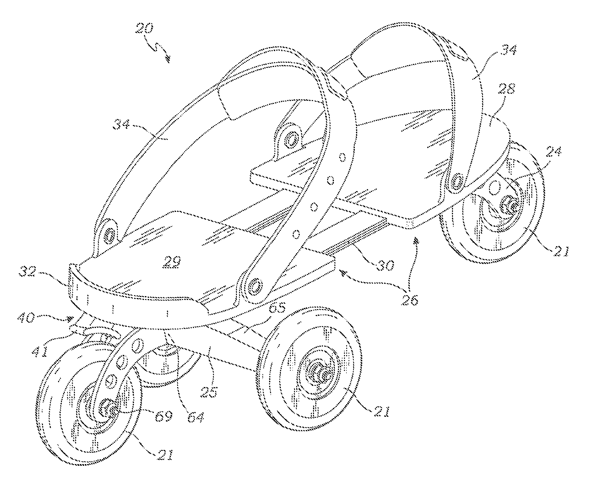
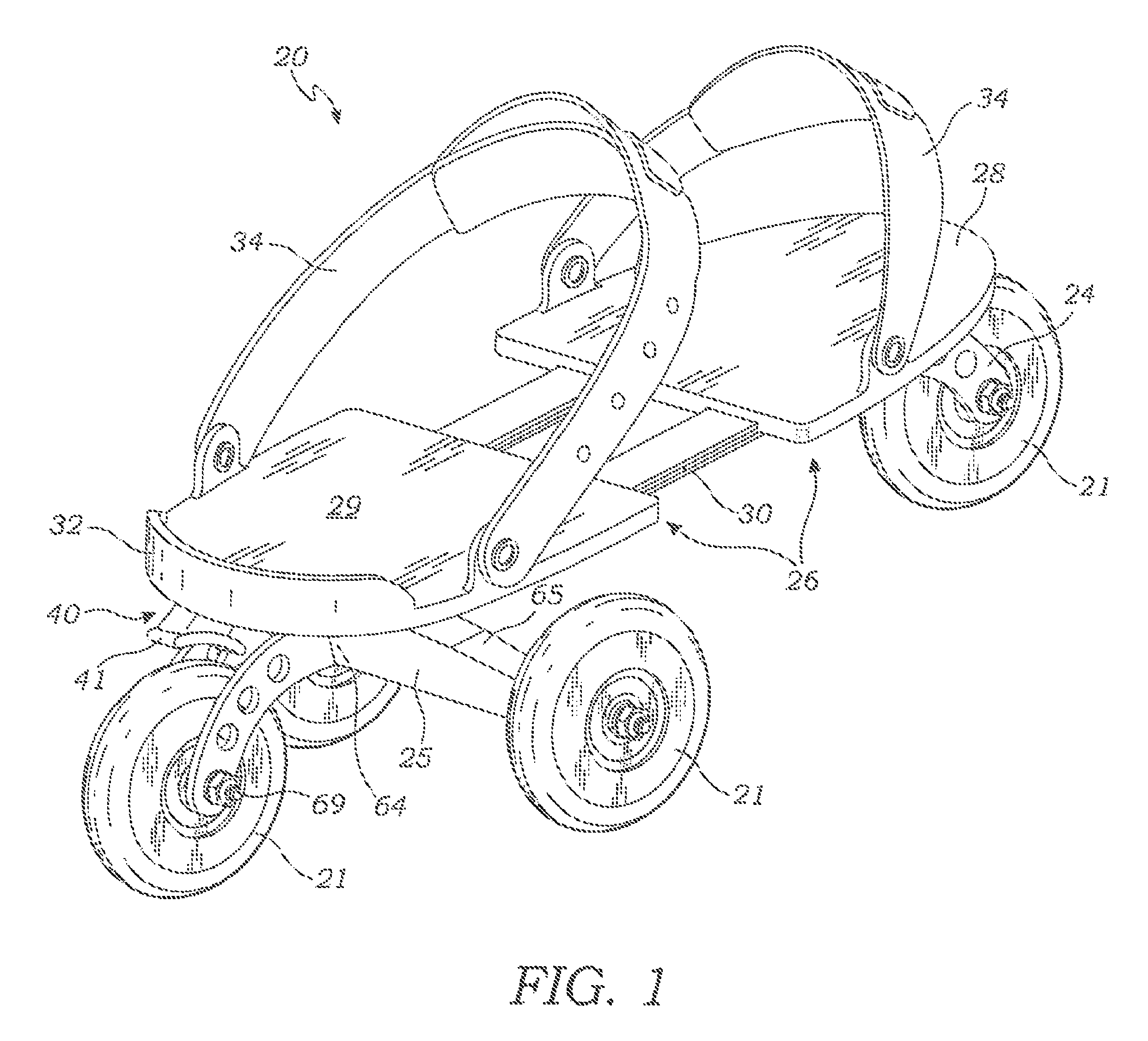
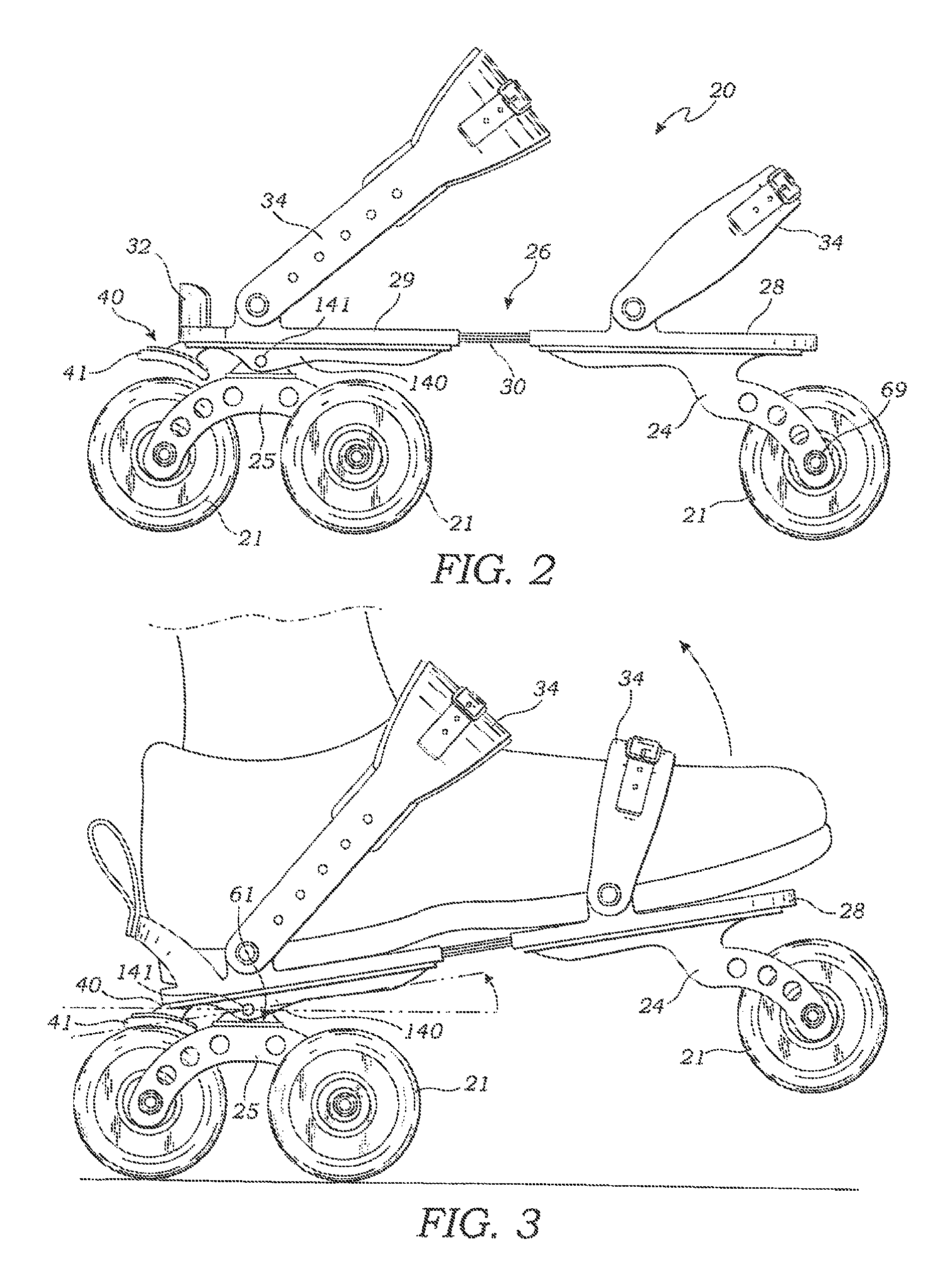
[0056]With reference to FIGS. 1-23, the present invention is directed to a roller skate 20, and particularly to a roller skate of the type adapted to be strapped onto or removably mounted on a skater's street shoe such as a sneaker, sandal, boot or the like. The roller skate preferably has four wheels 21 arranged in a diamond configuration with a single wheel positioned in the front of the skate and three wheels positioned at the rear of the skate to improve the skater's balance.

[0057]This skate includes a longitudinally adjustable platform 26 having a toe plate 28 and a heel plate 29 coupled together b...


PUM


Abstract

A roller skate having enhanced durability and stability is disclosed. The skate includes a platform for supporting a skater's foot. The platform includes a toe plate and heel plate connected by an adjustable connecting assembly. A front truck is affixed to the underside of the toe plate, while a rear truck is affixed to the underside of the heel plate. The front truck includes simple bracket arms for affixing a single front wheel which is capable of rotating, but not capable of tilting about the platform's longitudinal axis. Meanwhile, the rear wheel truck is mounted to the underside of the heel plate so as to permit both tilting movement about an inclined longitudinal axis, and also rotation about a transverse axis relative to the roller skate's platform. Preferably, the roller skate includes three wheels rotatably mounted to the rear wheel truck.

Description

RELATED APPLICATIONS[0001]The present application is a continuation-in-part of co-pending U.S. patent application Ser. No. 13 / 066,502 filed on Apr. 15, 2011, which in turn is a continuation-in-part of co-pending U.S. patent application Ser. No. 12 / 807,085 filed on Aug. 27, 2010, which in turn is a continuation-in-part of U.S. patent application Ser. No. 12 / 590,877 filed on Nov. 16, 2009 now U.S. Pat. No. 8,251,377 issued on Aug. 28, 2012.BACKGROUND OF THE INVENTION[0002]The present invention relates to wheeled skates, and more particularly to wheeled skates adaptable to be removably mounted upon a skater's footwear. The invention further relates to wheel trucks for mounting wheels on skates, skateboards, scooters and the like.[0003]Roller skates include wheels attached to the sole portion of a skate shoe. Conventional roller skates have a pair of front wheels sharing one axis of rotation and a pair of rear wheels sharing a second axis of rotation that is parallel to the first set of...

Claims


Application Information

Patent Timeline
Patent Type & Authority Patents(United States)
IPC IPC(8): A63C17/04
CPCA63C17/262A63C17/04A63C17/004A63C17/1418A63C17/0086
Inventor GREEN, BRIAN
Owner CARDIFF SPORT TECH
Why Eureka
Try Eureka