Apparatus and method of sterilizing inner walls of containers with a reflector apparatus

a technology of reflector and container, which is applied in the direction of meat/fish preservation using chemicals, containers preventing decay, energy-based chemical/physical/physico-chemical processes, etc. it can solve the problems of large radiation dose hitting the surface of the interior space of the container, the method of this type cannot be used, and the radiation dose cannot be large, so as to achieve the effect of high degree of efficiency of the sterilization devi

Inactive Publication Date: 2014-05-20
KRONES AG
View PDF13 Cites 12 Cited by
  • Summary
  • Abstract
  • Description
  • Claims
  • Application Information

AI Technical Summary

Benefits of technology

[0034]This is advantageous since the electron beam emitter usually has an outlet window for the discharge of the electron beams, which is larger in diameter than the interior space of the container to be sterilized.
[0035]As a result, a transition region should be formed in an advantageous manner between the opening of the reflector apparatus, which is connected to the electron beam emitter, and the opening of the reflector apparatus, which is capable of being introduced into the interior spac

Problems solved by technology

This could also lead to the deformation of and long-term damage to the containers to be sterilized, so that a method of this type cannot be used, in particular in the region of the production of plastics material containers.
On account of their function, however, treatment heads of this type have a minimum external diameter of approximately 16 mm and, in this way, although they can be inserted through the majority of container apertures, they cannot be inserted into conventional pre-forms since the internal diameter of these pre-forms is reduced with respect to the distal end, as viewed from the aperture.
This means that, if—instead of sterilizin

Method used


Image

  • Apparatus and method of sterilizing inner walls of containers with a reflector apparatus
  • Apparatus and method of sterilizing inner walls of containers with a reflector apparatus
  • Apparatus and method of sterilizing inner walls of containers with a reflector apparatus

Examples


Embodiment Construction

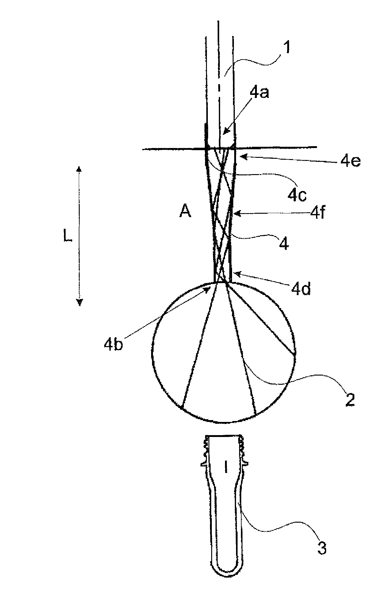
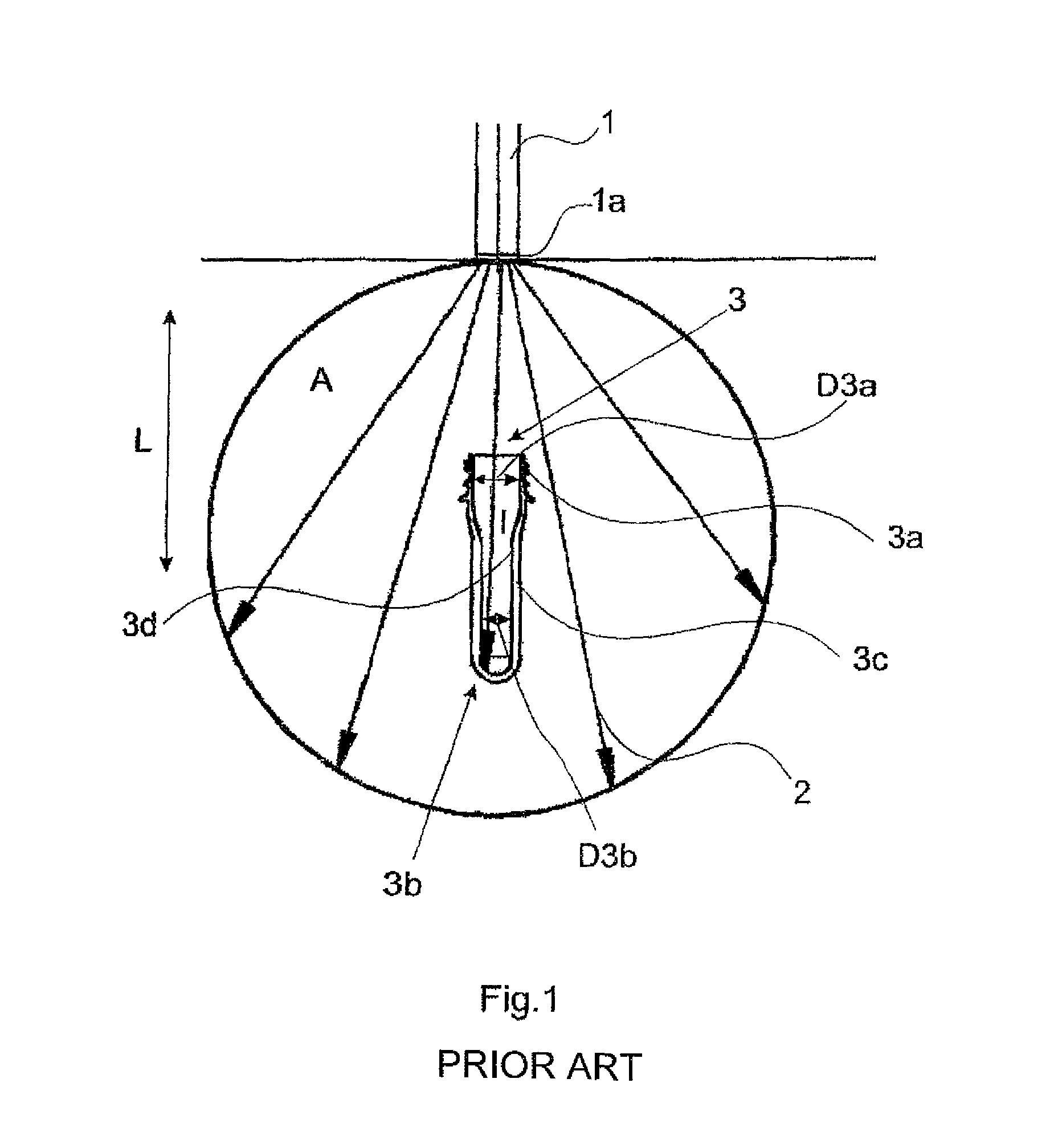
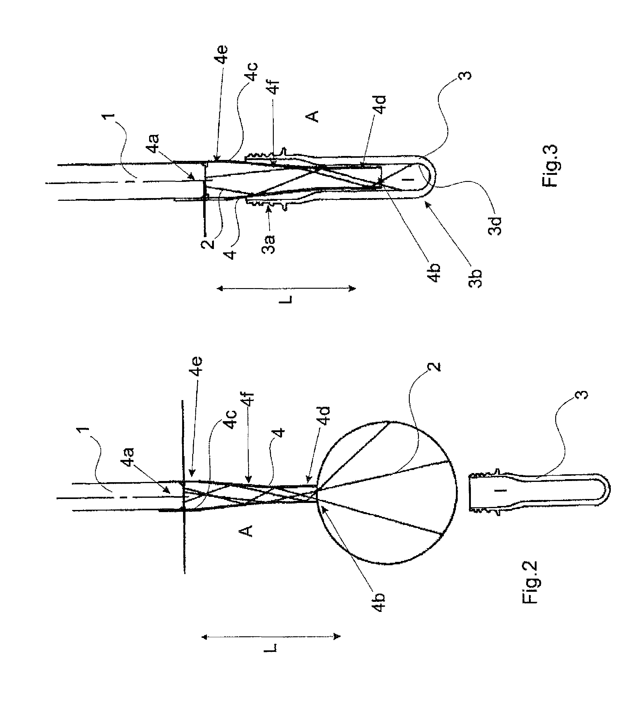
[0054]FIG. 1 is a basic drawing of a sterilization apparatus 1 or an electron beam emitter 1 known from the prior art for the sterilization of containers by means of electron beams 2 as well as an embodiment of a pre-form 3 and the striking of the electron beams 2 against this pre-form 3.

[0055]The illustrated embodiment of the pre-form 3 has a diameter D3a or internal diameter D3a respectively in the aperture area 3a which is larger than the diameter D3b or internal diameter D3b respectively of the lower area 3b, so that a complete sterilization at least of the lower area 3b of the pre-form 3, as already explained above, would take place by means of a radiation finger known from the known prior art.

[0056]Without a suitable apparatus such as the reflector apparatus, the electron beams 2 emitted by the electron beam emitter 1 can issue only in a non-directed manner out of the outlet window 1a and consequently arrive in part in the inner region I or the interior space I of the pre-form...


PUM

PropertyMeasurementUnit
Timeaaaaaaaaaa
Flow rateaaaaaaaaaa
Massaaaaaaaaaa

Abstract

An apparatus and a method of sterilizing inner walls of containers, wherein the apparatus has at least one electron beam emitter with at least one electron beam accelerator and an outlet window for the electron beams, a conveying device for conveying the containers to be sterilized and a reciprocating device for permitting a relative movement between the containers and the outlet window in a longitudinal direction of the containers. A reflector apparatus is connected to the electron beam emitter in a positively locking and/or friction locking manner at least locally in a region of the outlet window and is capable of being introduced at least locally during a defined period of time into an interior space of the container to be sterilized, in order to apply the electron beams to the inner walls of the container.

Description

BACKGROUND OF THE INVENTION[0001]The present invention relates to an apparatus and to a method of sterilizing inner walls of containers with at least one electron beam emitter.[0002]Apparatus for the sterilization of containers are incorporated for example in production and filling plants of container and bottle manufacturers, in order preferably to permit a sterilization of the interior space of the containers which is brought into contact with the medium to be received in the container.[0003]A sterilization of the containers can be carried out in this case by means of different methods. In this way for example, a liquid or flowable sterilization agent (chemical sterilization) can be applied to the inner wall of the container or the container can be immersed in an agent of this type, in which case, however, the container usually still has to be rinsed and dried after the sterilization in order to prevent a negative interaction between the sterilization agent and the filled medium.[...

Claims


Application Information

Patent Timeline
IPC IPC(8): A23B4/16A61L2/00B65B25/06A23L1/31G01N21/00B65D81/26A61L12/00A61L9/18B65D81/20A01N1/02B01J19/08A23L13/00
CPCA61L2/087B65B25/067A61L12/00A61L2/00G21K5/04A01N1/0294B65D81/2076A23B4/16A23L1/31A61L2202/23H01J33/02A61L9/18A61L2202/11B65D81/264A23L13/00
Inventor KNOTT, JOSEFKRUEGER, JOCHEN
Owner KRONES AG
Why Eureka
Try Eureka