Coordinate input device and display device including the same

a display device and input device technology, applied in the field of coordinate input devices, can solve problems such as parametric capacitance, and achieve the effect of enhancing capacitance detection precision and reducing random noise incorporated from display panels

Active Publication Date: 2014-05-20
PANASONIC INTELLECTUAL PROPERTY CORP OF AMERICA +1
View PDF9 Cites 20 Cited by
  • Summary
  • Abstract
  • Description
  • Claims
  • Application Information

AI Technical Summary

Benefits of technology

[0015]As described above, in the existing coordinate input device, it is difficult to always detect the capacitance with good precision by reducing random noise incorporated from the display panel, unfortunately.
[0016]Therefore, an object of the invention is to provide a technique capable of enhancing the capacitance detection precision by reducing random noise incorporated from a display panel.
[0019]According to the invention, random noise incorporated from the display panel can be reduced, thereby enhancing the capacitance detection precision.

Problems solved by technology

Insulators exist between the signal lines and the scanning lines on the screen of the display panel and between row electrodes and column electrodes in the sensor unit of the coordinate input device, so that parasitic capacitance occurs.

Method used


Image

  • Coordinate input device and display device including the same
  • Coordinate input device and display device including the same
  • Coordinate input device and display device including the same

Examples


first embodiment

[Entire Configuration]

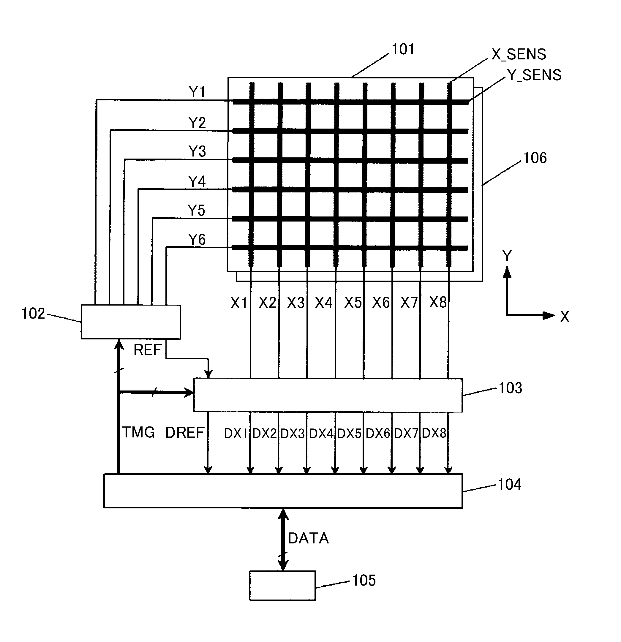
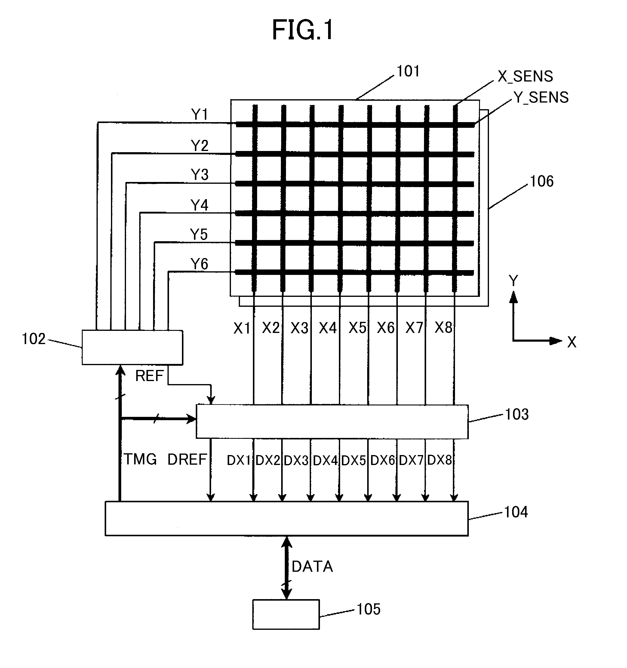
[0042]FIG. 1 is a block diagram for explaining the entire configuration of a display apparatus according to a first embodiment of the invention. Hereinafter, the entire configuration of the display apparatus according to the first embodiment will be described with reference to FIG. 1. Here, since a configuration of the display panel is the same as that of a display panel according to the related art, a coordinate input device will be described in detail in the following description. In addition, x and y in the figure represent x and y axes. Moreover, the display panel according to the first embodiment may be any one of non-light-emitting display panels such as a liquid crystal display panel and self-light-emitting display panels such as an organic EL display panel.

[0043]As illustrated in FIG. 1, the display apparatus according to the first embodiment includes a display panel 106 that displays an image based on display data (not shown) input from a system 105 wh...

second embodiment

[Entire Configuration]

[0080]FIG. 14 is a block diagram for explaining the entire configuration of a display apparatus according to the second embodiment. Hereinafter, the entire configuration of the display apparatus according to the second embodiment will be described with reference to FIG. 14. Here, the configurations of a coordinate input unit 101, a system 105, and a display panel 106 are the same as those of the first embodiment, in the following description, capacitance detection circuits 107 and 108 and an input coordinate computing circuit 109 will be described in detail.

[0081]As illustrated in FIG. 14, the coordinate input device according to the second embodiment includes the display panel 106 that displays an image based on display data (not shown) input from the system 105 which is an external apparatus, and a coordinate input device having the coordinate input unit 101 disposed on the display surface side of the display panel 106. The coordinate input device includes th...


PUM


Abstract

Provided is a coordinate input device including: a coordinate input unit having a plurality of first detection electrodes and a plurality of second detection electrodes; an electrode drive circuit that applies a drive signal to one or more of the detection electrodes; a capacitance detection circuit that detects a capacitance of the first and / or second detection electrode; means for selecting one or more of the detection electrodes to which the drive signal is not applied from among the detection electrodes which are disposed in parallel to the detection electrodes to which the drive signal is applied, as a reference electrode; means for detecting a capacitance of the selected reference electrode; means for correcting a capacitance detection result of the capacitance detection circuit on the basis of the detected capacitance of the reference electrode; and an input coordinate computing circuit that calculates an input coordinate from the corrected capacitance detection result.

Description

CROSS-REFERENCE TO RELATED APPLICATION[0001]The present application claims priority from Japanese application JP2010-044877 filed on Mar. 2, 2010, the content of which is hereby incorporated by reference into this application.BACKGROUND OF THE INVENTION[0002]1. Field of the Invention[0003]The present invention relates to a coordinate input device that detects an indication point on a screen, and a display apparatus having the same. More particularly, it is relates to a technique which is effective in increasing the coordinate detection precision of a display apparatus having a capacitive coupling type coordinate input device.[0004]2. Description of the Related Art[0005]A display apparatus having a detection device (hereinafter, also called a touch sensor or a touch panel) having a screen input function for inputting information by a touch operation (contact pressing operation, hereinafter, simply called a touch) using a finger or the like of a user on the display screen is used for ...

Claims


Application Information

Patent Timeline
Patent Type & Authority Patents(United States)
IPC IPC(8): G09G5/00
CPCG06F3/0418G06F3/044G06F3/0446G06F3/04184G06F3/04182G06F2203/04111G06F3/047
Inventor MAMBA, NORIONAGATA, KOJIHAYAKAWA, KOJI
Owner PANASONIC INTELLECTUAL PROPERTY CORP OF AMERICA
Why Eureka
Try Eureka