Door arrangement and guide of a door

a technology of door and guide, which is applied in the direction of wing accessories, transportation and packaging, and wing arrangements, etc., can solve the problems of increasing the wear of the surface and bearing of the roll, increasing the need for repair, and reducing the jamming of the automatically movable door. , the effect of reducing the need for repair

Active Publication Date: 2014-05-27
KONE CORP
View PDF23 Cites 5 Cited by
  • Summary
  • Abstract
  • Description
  • Claims
  • Application Information

AI Technical Summary

Benefits of technology

[0007]The object of the invention is to eliminate, among others, the aforementioned drawbacks of prior-art solutions. More particularly the purpose of the invention is to produce a door arrangement and a guide of the door that are improved in terms of their wear behavior. The purpose of the invention is further to produce one or more of the following advantages, among others:
[0008]A better door arrangement and guide, in terms of their susceptibility to malfunction (e.g. jamming or wearing) are achieved.
[0017]In one embodiment of the invention the vertical supporting of the door panel is in the top part of the door panel and the bottom side is supported only in the lateral direction. This can be performed by means of the aforementioned guide rail, from which the aforementioned at least one guide can take lateral support force. In this way it does not need to rest on the base of the groove, into which possible dirt sinks. Thus the jamming of an automatically movable door can be reduced and the need for repair decreased and the availability of the elevator or of the building remains good.
[0032]In one embodiment of the invention the sliding guide part comprising the aforementioned sliding guide surface is an integral part of the guide frame. One advantage is an inexpensive and simple structure.
[0038]In one embodiment of the invention the sliding guide surface(s) is / are arranged to be able to move into contact with the guide surface of the guide rail only after the guide roll has worn by a certain amount. In one embodiment of the invention the greatest distance between the outer rims of the first and the second guide roll in the lateral direction of the guide rail is greater than the greatest distance between the sliding guide surfaces (4,4″;4′,4′″) in the lateral direction of the guide rail. Thus it can be simply implemented that the sliding guide surface(s) is / are able to move into contact with the guide surface of the guide rail only after the guide roll has worn by a certain amount. On the other hand, one advantage is that before there is abundant wear, the sliding guide surfaces prevent rotation of the guide.

Problems solved by technology

Sliding parts, however, wear quickly and a problem therefore is rapid impairment of the quality, e.g. the evenness, of the slide.
One problem with these types of solutions is the continuously repeated change of rotation direction of the roll, which change always occurs when the roll swings in the lateral direction from the guidance of a first guide rail surface to a second.
This increases the wearing of the surface and bearing of the roll and at its worst might cause noise.
A problem in this case is also that, e.g. as a result of becoming dirty, the roll is not necessarily able to rotate freely and starts to slide against the surfaces of the guide rail, thus being in contact with the surface of two guides at the same time, which might increase the wearing.
A problem in all these solutions is that as the primary guide element (roll or sliding shoe) of a guide wears, its dimensions change so that the clearances of the guide increase to be such that the sliding door no longer travels evenly and might produce noise.
After the occurrence of this wearing problem, the sliding guide part must be replaced very quickly, because the sliding guide quickly loses its usability completely.

Method used


Image

  • Door arrangement and guide of a door
  • Door arrangement and guide of a door
  • Door arrangement and guide of a door

Examples


Embodiment Construction

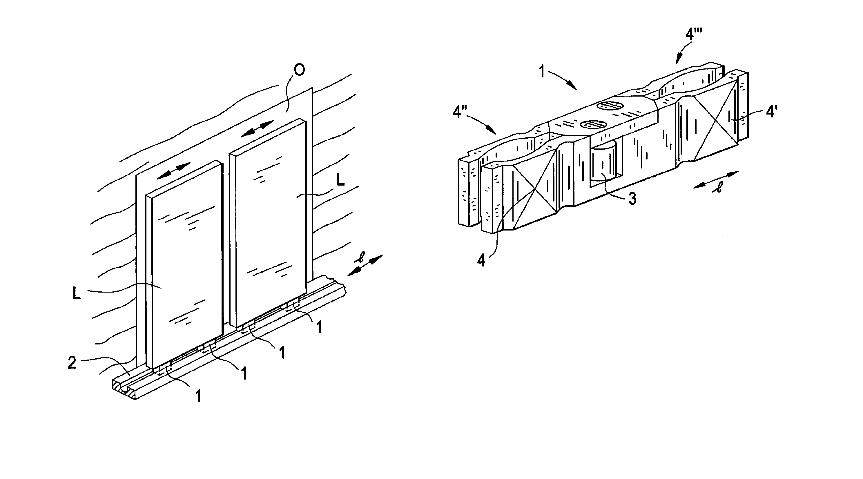
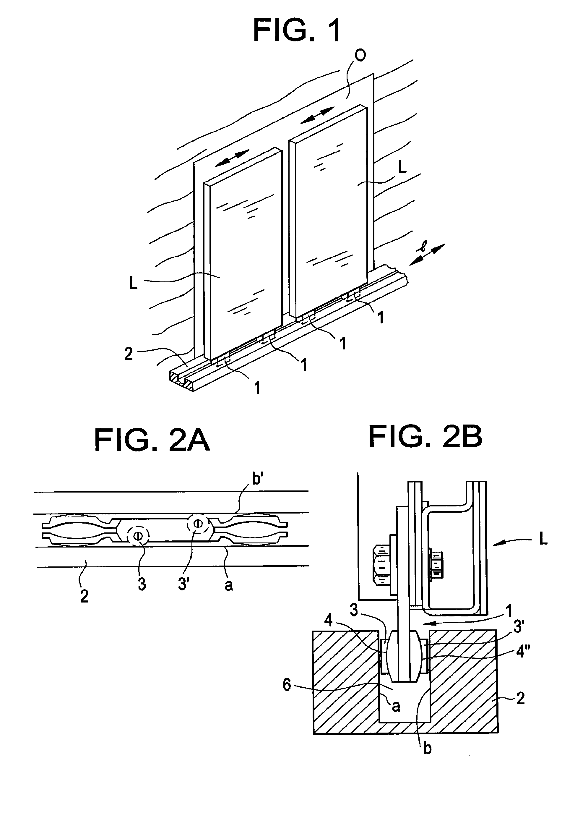
[0056]FIG. 1 presents an indicative three-dimensional view of a door arrangement according to the invention. In the arrangement the door panel L is arranged to move on a path of movement controlled by the guide arrangement in front of the access opening O between a position that covers the access opening and a position that covers the access opening less. The access opening O can be the door opening of an elevator car, the opening of a landing door of an elevator, or some other access opening of the building, e.g. an entrance to a building or to a part of a building. The door panel preferably receives its operating power from an actuator (not shown), such as e.g. an electric motor or a linear motor.

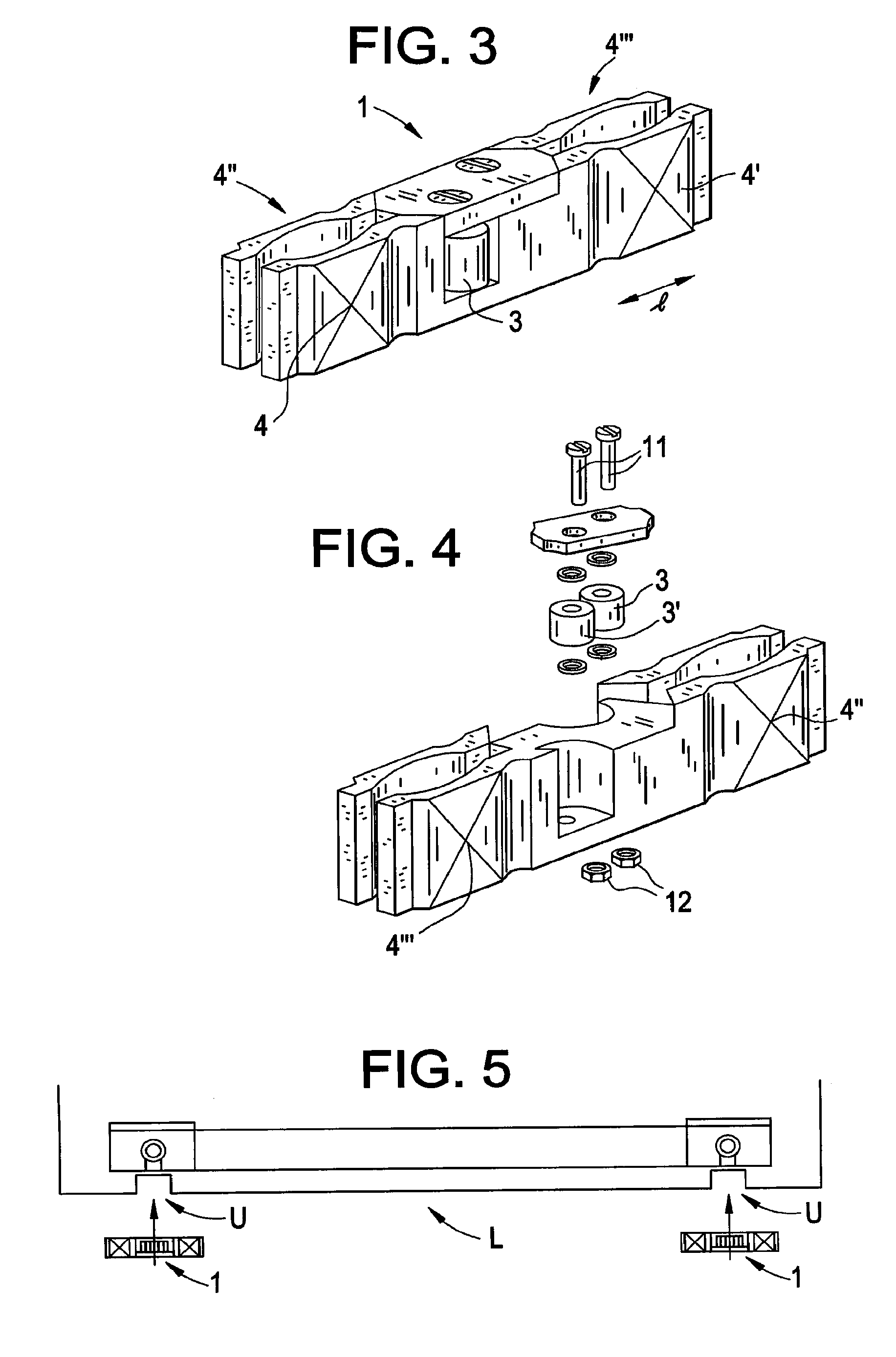
[0057]The guide arrangement for controlling the path of movement of a door panel L comprises two guides 1 rigidly supported on the door panel that are at a distance from each other and disposed on the bottom edge of the door panel, and a guide rail 2, closely along which the aforementione...


PUM


Abstract

Door arrangement, more particularly a sliding door arrangement of an automatic door of an elevator or of a building, which comprises a door panel, and a guide arrangement for controlling the path of movement of the door panel, which guide arrangement comprises at least one guide connected to the aforementioned door panel, and a guide rail, closely along which the aforementioned guide is arranged to move, and from which guide rail the guide takes lateral support force with respect to the longitudinal direction of the guide rail. The guide comprises a first guide roll for taking the support force from the guide surface of the guide rail on the side of a first side of the guide, and a second guide roll for taking support force from the guide surface of the guide rail on the side of a second side of the guide.

Description

CROSS-REFERENCE TO RELATED APPLICATIONS[0001]This application is a continuation of International Application Number PCT / FI2010 / 000054 filed on Sep. 2, 2010 and claims priority to Finnish Application Number FI 20090317 filed on Sep. 3, 2009, the entire contents of each of which are hereby incorporated herein by reference.FIELD OF THE INVENTION[0002]The object of the invention is a door arrangement and a guide of a door.BACKGROUND OF THE INVENTION[0003]Roller guide shoes or sliding guides connected to a door panel are used in the prior-art sliding doors of an elevator or of automatic doors for guiding the door panel, which guide shoes or sliding guides guide closely following a guide rail by taking support force that is lateral with respect to the direction of movement of the guide from the guide rail. The guides are generally disposed on the top edge and / or on the bottom edge of the door panel. The guide rails are generally disposed in the floor of the building or corresponding or in...

Claims


Application Information

Patent Timeline
Patent Type & Authority Patents(United States)
IPC IPC(8): E05D15/00E05D13/00
CPCE05Y2600/46B66B13/301E05Y2900/104B66B13/08E05D15/0656E05D15/06E06B3/46
Inventor RAHARDJO, ANDHIKAPUTRAKEMPPAINEN, KARI
Owner KONE CORP
Why Eureka
Try Eureka