Lash crossing detection using a shaft torque sensor

Active Publication Date: 2014-05-27
FORD GLOBAL TECH LLC
View PDF16 Cites 8 Cited by
  • Summary
  • Abstract
  • Description
  • Claims
  • Application Information

AI Technical Summary

Benefits of technology

The patent text describes a method that solves problems with estimating speed using speed sensors alone. The method is based on changes in position readings and is less affected by noise and disturbances. It is efficient and accurate even at high speeds.

Problems solved by technology

Lash crossing has been one of the key factors contributing to drivability issues.
Using the measurements available on production vehicles today, reliable detection of the crossing the deadband zone is a formidable challenge.
The numerical and resolution problems associated with estimation methods solely based on speed sensors position (tooth count) readings, remain limited to higher speed operation and are sensitive to various noise factors: synchronization, resolution at low speeds, engine and road disturbances, measurement and numerical errors, to name a few.

Method used


Image

  • Lash crossing detection using a shaft torque sensor
  • Lash crossing detection using a shaft torque sensor
  • Lash crossing detection using a shaft torque sensor

Examples


Embodiment Construction

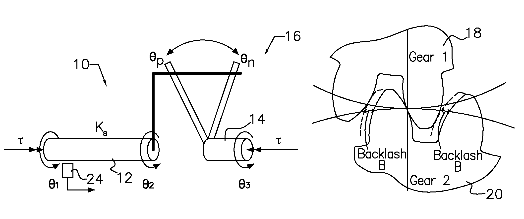
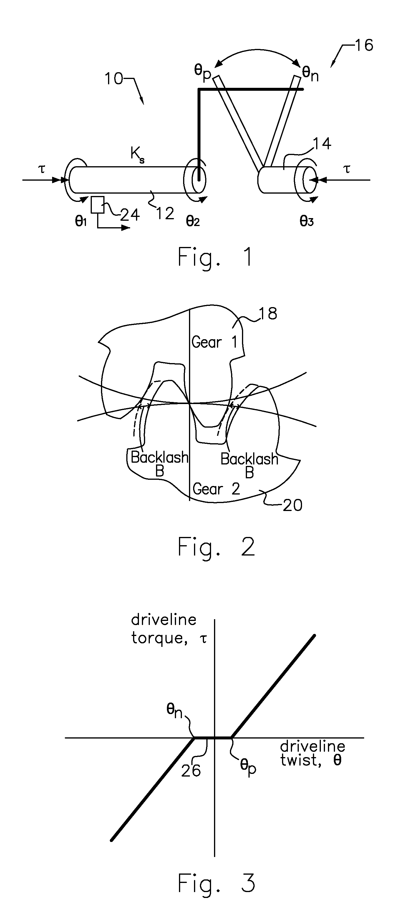
[0019]FIG. 1 shows a driveline 10 having two shafts 12, 14 connected by a torsional discontinuity 16 in which backlash can occur. The discontinuity 16 is be represented by the meshing gears 18, 20 of FIG. 2, each gear being secured to one of the shafts 12, 14. A production-suitable magneto-elastic shaft torque sensor 24 having ability to measure torque directly at a transmission input shaft or output shaft is enabling many features in vehicle control. The dynamic response of the shaft torque sensor 24 is within a fraction of a millisecond and its accuracy is far superior to any currently available on-board torque estimates. Hence, this torque measurement can enable robust backlash detection and useful feedback for drivability control of motor vehicles.

[0020]FIG. 3 is a graph showing the variation of driveline torque τ and twist θ from a negative twist angle to positive twist angle including discontinuities θn, θp where entry into or exit from a backlash zone 26, i.e., a lash crossin...


PUM


Abstract

A method for detecting backlash and adjusting driveline variables, includes measuring torque transmitted between components across a torsional discontinuity, measuring driveline twist across the discontinuity, using a ratio of driveline twist divided by torque and an inverse of driveline stiffness to determine whether the driveline is entering, exiting or in a backlash zone, and using measured driveline twist and torque at the backlash zone to adjust reference values of driveline twist and torque.

Description

BACKGROUND OF THE INVENTION[0001]1. Field of the Invention[0002]This invention relates generally to detecting a lash crossing in a motor vehicle driveline particularly with the use of a device that produces signals indicating the magnitude of torque being transmitted and the directional sense of the transmitted torque.[0003]2. Description of the Prior Art[0004]Automotive drivetrains include meshed gear teeth that exhibit deadband when the direction of torque applied to them changes, as shown in the diagram of FIG. 1 and in FIG. 2.[0005]Such deadband causes discontinuity of the transmitted torque and excitation of the driveline, as the shafts feature certain compliance. Due to that, the deadband is typically called “backlash” or being in the deadband zone during the change of direction of torque: “lash crossing.” If there were no backlash associated with the meshed gears, the shaft twist to torque relationship could have been expressed using the torsional spring equation (Hooke's law...

Claims


Application Information

Patent Timeline
IPC IPC(8): G01M13/02G01L3/02
CPCG01M13/021G01M13/02G01L3/02
Inventor YANAKIEV, DIANATSENG, ERIC H.PIETRON, GREGORY M.FUJII, YUJI
Owner FORD GLOBAL TECH LLC
Why Eureka
Try Eureka