Optical encoder

a technology of optical encoder and encoder, applied in the field of optical encoder, can solve the problems of error becoming position detection error, error from ideal sine wave, etc., and achieve the effect of high-accuracy position detection and reducing error components of detected waveform

Inactive Publication Date: 2014-05-27
CANON KK
View PDF4 Cites 6 Cited by
  • Summary
  • Abstract
  • Description
  • Claims
  • Application Information

AI Technical Summary

Benefits of technology

[0009]According to the above-mentioned configuration, unnecessary spatial frequency components generated by interference between diffracted light beams in an image received on a light receiving surface of the light receiving element array and unnecessary spatial frequency components included in the transmittance distribution or the reflectance distribution in the scale track can be reduced, and error components of a detected waveform can be reduced. Therefore, high-accuracy position detection is enabled.

Problems solved by technology

An error from an ideal sine wave occurs due to this effect.
As a result, the error becomes a position detection error when the sine wave is converted into a position signal by an arc tangent operation.

Method used


Image

  • Optical encoder
  • Optical encoder
  • Optical encoder

Examples


Embodiment Construction

[0026]Various exemplary embodiments, features, and aspects of the invention will be described in detail below with reference to the drawings.

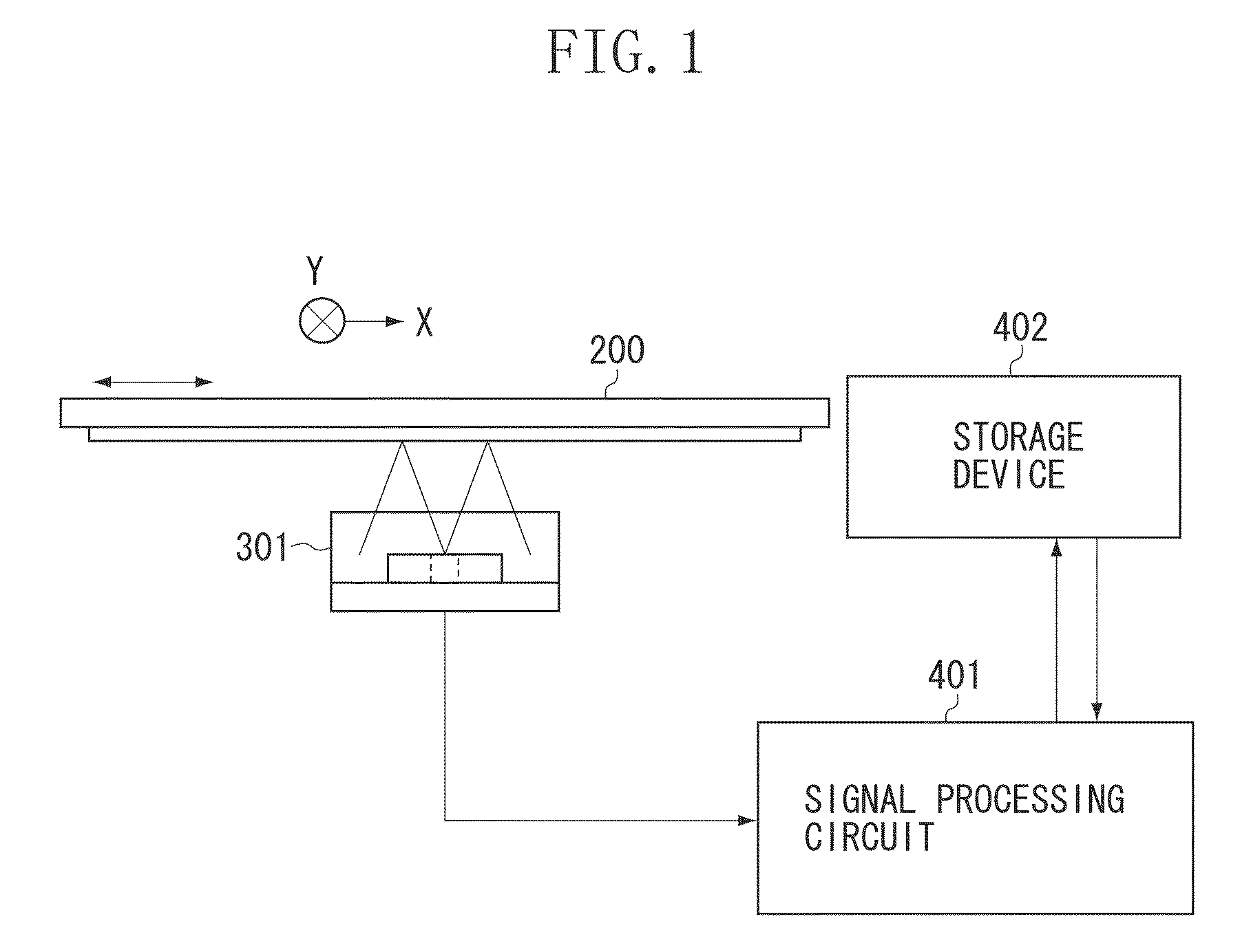
[0027]FIG. 1 illustrates a configuration of an optical encoder according to a first exemplary embodiment of the present invention. The optical encoder includes a displacement scale 200 attached to a movable member, a sensor unit 301 attached to a fixed member, a signal processing circuit 401 serving as a control unit, and a storage device 402. The signal processing circuit 401 serving as the control unit performs interpolation processing of an encoder signal obtained from the sensor unit 301, writes and reads a signal to and from the storage device 402, and outputs a position signal.

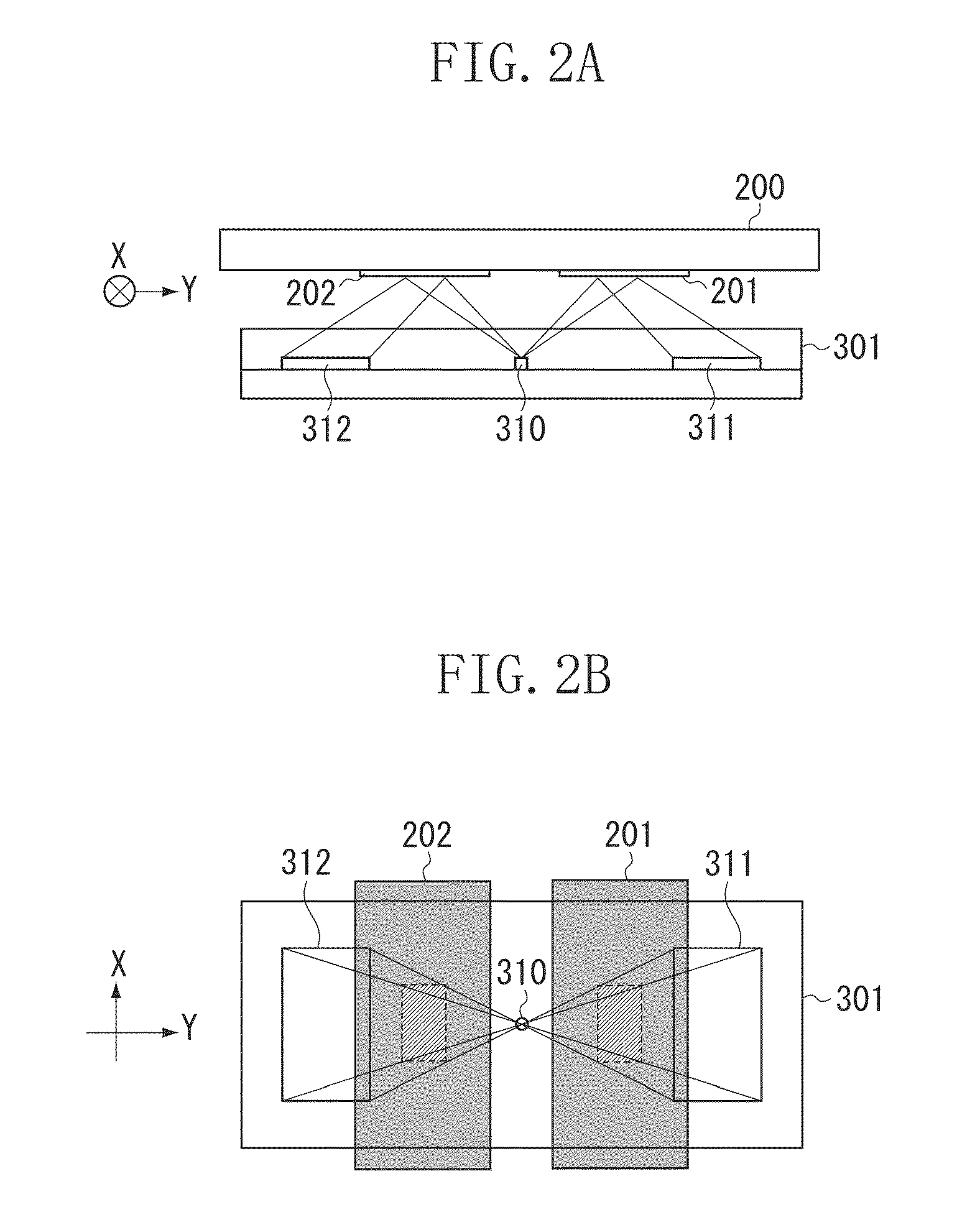
[0028]FIGS. 2A and 2B illustrate a configuration of the sensor unit 301, where FIG. 2A is a side view, and FIG. 2B is a top view.

[0029]The sensor unit 301 is an integrated light receiving and emitting sensor unit in which a light emitting diode (LED) 310 serving as ...


PUM


Abstract

In order to reduce an error component of a detected waveform and enable high-accuracy position detection, there is provided an optical encoder, in which a transmittance distribution or a reflectance distribution provided in a scale track in a displacement scale has a first modulation period and a second modulation period in a scale displacement direction, the light receiving element array is arranged to detect a first signal group including two-phase signals, relative phases of which are reversed, in the first modulation period and a second signal group including two-phase signals, relative phases of which are reversed, in the second modulation period, first position information in the first modulation period is detected from the first signal group, and second position information in the second modulation period is detected from the second signal group, and the second modulation period is an odd multiple of the first modulation period.

Description

BACKGROUND OF THE INVENTION[0001]1. Field of the Invention[0002]The present invention relates to an optical encoder that detects a position, and more particularly, to an optical encoder that detects position information relating to a focus lens and a zoom lens included in a lens apparatus such as a still camera or a video camera.[0003]2. Description of the Related Art[0004]Conventionally, an encoder is used to detect a position of a machine tool or a factory automation (FA) apparatus. A position detection system for the encoder is roughly classified into an incremental system for measuring a relative movement distance and an absolute system for detecting an absolute position. The encoder using the incremental system has the advantage that its configuration may be simple while having disadvantages in that position information is lost when power thereto is turned off, and errors are accumulated by external noise. On the other hand, the encoder using the absolute system generally has t...

Claims


Application Information

Patent Timeline
Patent Type & Authority Patents(United States)
IPC IPC(8): G01D5/34
CPCG01D5/34784G01D5/26G01D5/347G01D5/28
Inventor NAGURA, CHIHIRO
Owner CANON KK
Why Eureka
Try Eureka