Apparatus for optically recording and reproducing information

Inactive Publication Date: 2007-08-09
CANON KK
View PDF13 Cites 6 Cited by
  • Summary
  • Abstract
  • Description
  • Claims
  • Application Information

AI Technical Summary

Benefits of technology

[0015]According to the present invention, an area where zeroth-order diffracted beams and first-order diffracted beams interfere with each other is reduced, and at the same time, an area where only the zeroth-order diffracted beams lie is increased by increa

Problems solved by technology

At this time, when an object lens crosses tracks of the optical disk, interference is superposed on focusing signals by first-order diffracted beams reflected by the tracks composed of lands and grooves that are formed on the optical disk, resulting in fluctuations in the focusing signals.
This causes unstable focusing servo control, actuator noise depending on the interference, and the like.
However, the areas where the zeroth-order diffracted beams and the first-order diffracted beams interfere with each other can be increased as show

Method used


Image

  • Apparatus for optically recording and reproducing information
  • Apparatus for optically recording and reproducing information
  • Apparatus for optically recording and reproducing information

Examples


Example

First Exemplary Embodiment

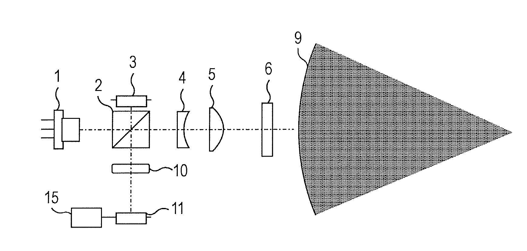
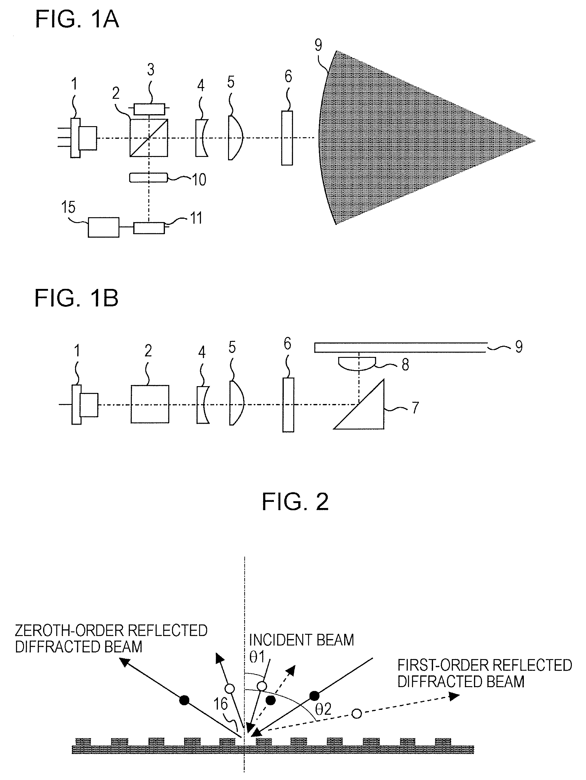
[0031]FIGS. 1A and 1B are schematic diagrams of an optical system of an apparatus for optically recording and reproducing information according to a first exemplary embodiment of the present invention.

[0032]First, the general outlines of the optical system will be described.

[0033]Light beams emitted from a semiconductor laser (LD) 1 are partly reflected from a polarizing beam splitter (PBS) 2, and are incident on a monitoring photodiode (PD) 3 for monitoring. Outputs from this monitoring PD 3 for monitoring are used for controlling the output power of the LD 1.

[0034]Light beams passing through the PBS 2 are incident on a collimating lens unit including a first lens 4 and a second lens 5, and become substantially parallel to each other. These parallel beams pass through a quarter-wave plate 6, are deflected by a mirror 7, and are focused on an optical disk 9 by an objective lens 8. During recording of information, light beams output from the LD 1 are modulat...

Example

Second Exemplary Embodiment

[0069]FIGS. 7A and 7B are schematic diagrams of an optical system of an apparatus for optically recording and reproducing information according to a second exemplary embodiment of the present invention.

[0070]The outward optical system from the LD 1 to the objective lens 8 is the same as that of the first exemplary embodiment.

[0071]An inward optical system will now be described. Light beams reflected from the optical disk 9 are incident on the PBS 2 via the objective lens 8, the quarter-wave plate 6, and the collimating lens unit including the first lens 4 and the second lens 5. These incident beams are reflected from the PBS 2, and are incident on a diffractive element 12 serving as a wavefront splitting element. The light beams passing through the diffractive element 12 are focused on a PD 14 for generating RF signals and servo control signals via a sensor lens 13. Information signals and servo control signals are obtained from the output from the PD 14 a...


PUM


Abstract

An apparatus for optically reproducing and recording information includes a light source, an objective lens, a light detecting element, and a processor. The objective lens focuses light beams emitted from the light source on an optical recording medium having tracks disposed at a track pitch. The wavelength of the light beams is greater than the track pitch of the medium. The light detecting element receives light beams reflected from the medium. The light detecting element includes a first region that receives substantially only light beams generated by interference between zeroth-order diffracted beams and first-order diffracted beams among the light beams reflected from the tracks of the medium and a second region that receives substantially only the zeroth-order diffracted beams. The processor generates focusing error signals using astigmatic focusing error detection on the basis of an output from the second region of the light detecting element.

Description

BACKGROUND OF THE INVENTION[0001]1. Field of the Invention[0002]The present invention relates to apparatuses for optically recording and reproducing information namely for recording information on optical recording media such as optical disks or for reproducing information recorded on optical recording media. In particular, the present invention relates to generating focusing error signals.[0003]2. Description of the Related Art[0004]Optical disk devices have been widely applied in various fields, and have been developed for use as recording devices for video recorders, video cameras, and the like.[0005]When focusing attention on technologies for generating servo errors in optical pickup elements in the optical disk devices, astigmatic focusing error detection has been mainly used for generating focusing errors since the early days of compact disk devices.[0006]In the astigmatic focusing error detection, as is generally known, astigmatism is introduced into a light detecting optical...

Claims


Application Information

Patent Timeline
IPC IPC(8): G11B7/00
CPCG11B7/0909G11B7/1381G11B7/133G11B7/09G11B7/1353
Inventor NISHIKAWA, KOICHIRO
Owner CANON KK
Why Eureka
Try Eureka