Method for automatically creating a defined face opening in longwall mining operations

a technology of defined face and mining operations, which is applied in the direction of mine roof supports, slitting machines, surface mining, etc., to achieve the effect of removing errors caused by component vibration

Active Publication Date: 2013-10-29
BEIJING CCRI TIANMA AUTOMATION TECH CO LTD +1
View PDF12 Cites 7 Cited by
  • Summary
  • Abstract
  • Description
  • Claims
  • Application Information

AI Technical Summary

Benefits of technology

[0007]The advantage is connected to the present invention that, primarily on the basis of the shield height, which is to be ascertained with comparatively little effort, a parameter is available in sufficient precision and reliability for the longwall control. The other parameters used according to the invention comprise the detection of the cutting guidance of the extraction machine by establishing its absolute cutting height. Because the top canopy of the shield support frame first reaches the area exposed by the extraction machine as it travels past the relevant shield support frame with a time delay, i.e., with a so-called support delay of one to two support steps, the invention provides that the corresponding data sets for each section of the longwall operation stepped through by an assigned shield support frame are stored and compared in terms of a location-synchronous analysis. On the basis of this measure, a statement is possible about whether the cutting height exposed by the extraction machine also corresponds to the later shield height at this location, or whether possibly occurring strata collapse or occurring convergences result in deviations of the shield height upward or downward from the cutting height, which are to be taken into consideration the next time the extraction machine travels past, by a change or adaptation of its cutting height. This also applies correspondingly for the passage of troughs and / or saddles. The method according to the invention thus essentially uses the ascertained shield height in order to set up a control loop for controlling the extraction and support work with incorporation of the cutting height of the extraction machine, which results in automatic maintenance of a defined face opening upon its application. The shield height perpendicular to the bed, which is ascertained at the front edge of the top canopy between the upper edge of the top canopy and the lower edge of the skid, can expediently be used as an indicator for the longwall height. The shield height in the area of the shield prop is also suitable as a control variable for the height control of the particular shield support frame, because otherwise the relative angle between the top canopy and the floor skid in individual height adaptation phases results in strong height changes in relation to the canopy tip. It can thus be expedient to ascertain the shield height between top canopy and floor skid at arbitrary positions and to use the most advisable position for the particular method for the height control.
[0018]According to one exemplary embodiment of the invention, it is provided that acceleration sensors are used as the inclination sensors, which detect the angle of the acceleration sensor in space via the deviation from the Earth's gravity. The angle in relation to the vertical is thus determined physically, which is to be converted into the angle of inclination for the inclination of the shield components to the horizontal. It can be provided, to eliminate errors caused by the vibrations of the components used, that the measured values ascertained by the acceleration sensors are checked and corrected using a suitable damping method.

Problems solved by technology

One problem in the automatic control of longwall operations, both in the mining direction and also in the extraction direction of the extraction machine, is, inter alia, to produce a sufficiently large face opening, in order to ensure the passage of the longwall equipment without collisions between extraction machine and shield support frames, for example as the extraction machine travels past, on the one hand, and to keep the rock collapse during the extraction work as limited as possible, and accordingly to restrict the extraction work to the seam horizontal as much as possible, without also cutting excessive country rock, on the other hand.

Method used


Image

  • Method for automatically creating a defined face opening in longwall mining operations
  • Method for automatically creating a defined face opening in longwall mining operations
  • Method for automatically creating a defined face opening in longwall mining operations

Examples


Embodiment Construction

[0027]The foundations of the method according to the invention are explained in greater detail on the basis of the figures explained hereafter.

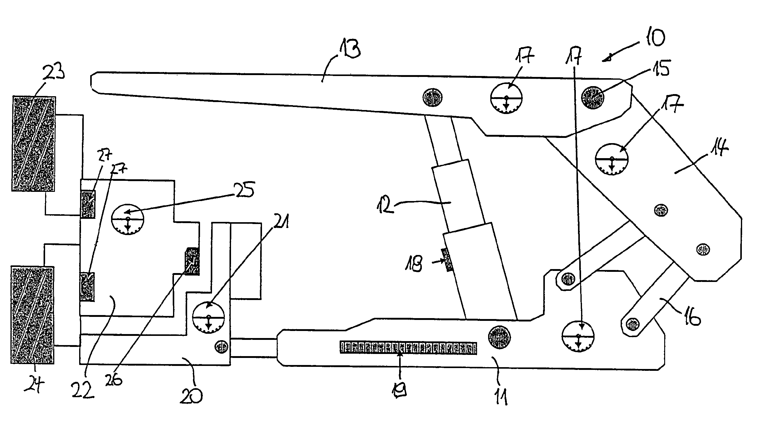
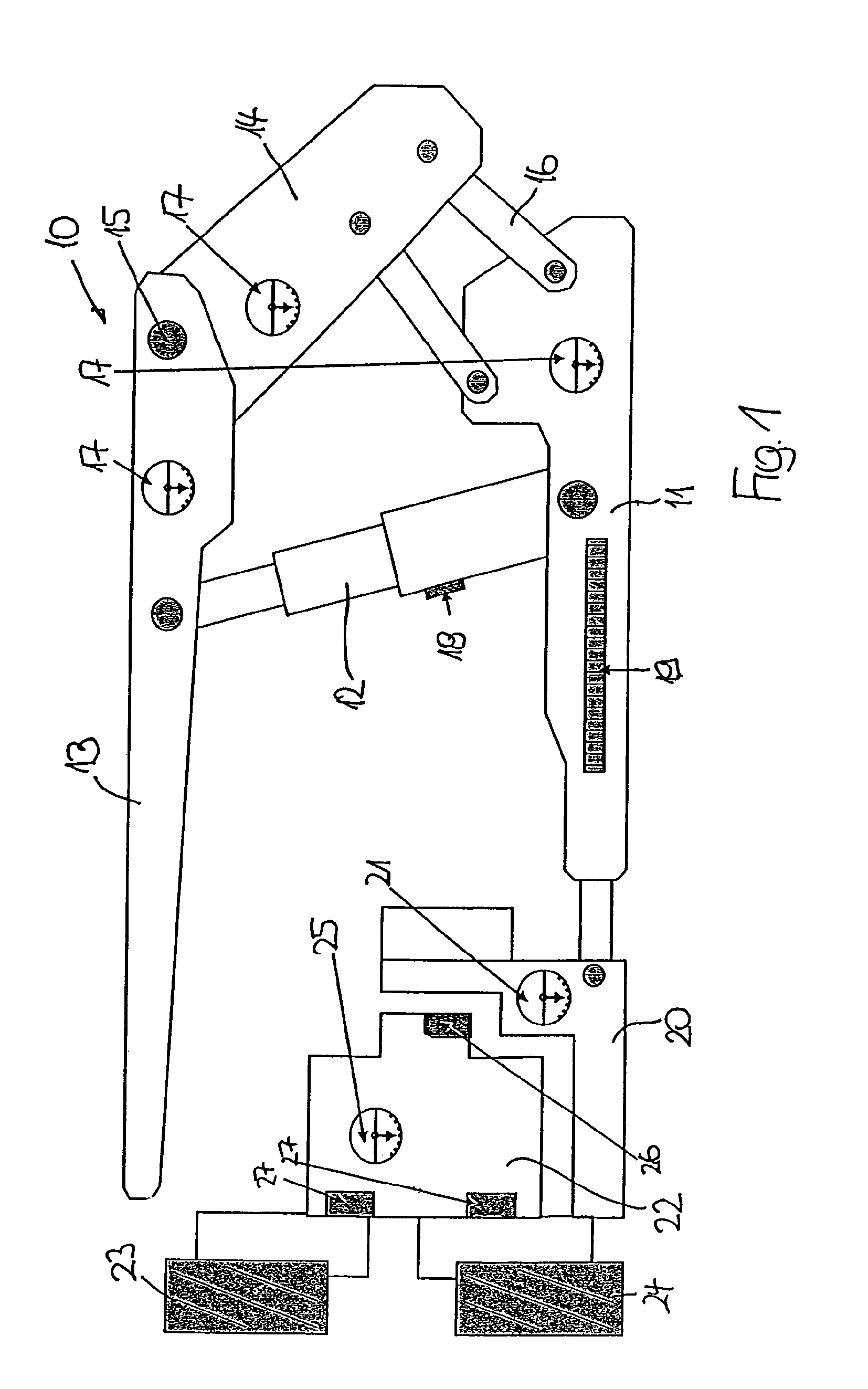
[0028]The longwall equipment shown in FIG. 1 primarily comprises a shield support frame 10 having a floor skid 11, on which two props 12 are attached in a parallel configuration, of which only one prop is recognizable in FIG. 1, which carries a top canopy 13 on its upper end. While the top canopy 13 protrudes in the direction of the extraction machine (to be described hereafter) at its front (left) end, a gob shield 14 is linked on the rear (right) end of the top canopy 13 using a joint 15, the gob shield being supported by two supporting connection rods 16, which rest on the floor skid 11 in the side view. In the exemplary embodiment shown, three inclination sensors 17 are attached to the shield support frame 10, one inclination sensor 17 on the floor skid 11, one inclination sensor 17 in the rear end of the top canopy 13 in proximity to the...


PUM


Abstract

A method for automatically producing a defined face opening in a longwall mining operation, in underground coal mining, having a face conveyor, at least one extraction machine and hydraulic shield support frames. Inclination sensors are disposed on at least three of the four main components of each shield support frame, such as floor skid, gob shield, support connection rods and gob-side area of the top canopy. From ascertained inclination data, by comparison with base data defining a geometrical orientation of the components and a movement thereof during stepping, a respective shield height of the shield support frames perpendicular to a bed thereof is calculated. From further sensors on the extraction machine, a cutting height thereof is acquired as a face opening. In terms of a location-synchronous analysis, for possible adjustment purposes the cutting height is compared with the shield height when the shield support frame, which trails the extraction machine with a time delay, has reached the position to which relates that cutting height which was used in the comparison.

Description

BACKGROUND OF THE INVENTION[0001]The instant application should be granted the priority date of Feb. 19, 2008, the filing date of the corresponding International patent application PCT / EP2008 / 001266.[0002]The invention relates to a method for automatically creating a defined face opening in longwall mining operations, having a face conveyor, at least one extraction machine, and a hydraulic shield support, in underground coal mining.[0003]One problem in the automatic control of longwall operations, both in the mining direction and also in the extraction direction of the extraction machine, is, inter alia, to produce a sufficiently large face opening, in order to ensure the passage of the longwall equipment without collisions between extraction machine and shield support frames, for example as the extraction machine travels past, on the one hand, and to keep the rock collapse during the extraction work as limited as possible, and accordingly to restrict the extraction work to the seam...

Claims


Application Information

Patent Timeline
Patent Type & Authority Patents(United States)
IPC IPC(8): E21C35/14
CPCE21C35/14E21C35/24E21C41/16E21D23/0004E21D23/0034E21D23/0043E21D23/12
Inventor JUNKER, MARTINMOZAR, ARMIN
Owner BEIJING CCRI TIANMA AUTOMATION TECH CO LTD
Why Eureka
Try Eureka