Method and apparatus for transmitting and receiving control information in multi-antenna system

a control information and multi-antenna technology, applied in the field of multi-antenna systems or multiple-input multiple-output systems, can solve the problems of inability to provide correct information to users, low efficiency of fec techniques in a good channel environment, and so as to reduce the frequency of using pdcch and reduce the waste of downlink resources

Active Publication Date: 2014-05-27
SAMSUNG ELECTRONICS CO LTD
View PDF1 Cites 20 Cited by
  • Summary
  • Abstract
  • Description
  • Claims
  • Application Information

AI Technical Summary

Benefits of technology

[0018]Another aspect of the present invention is to provide a method and apparatus capable of improving the system capacity by reducing the frequency of using a PDCCH.
[0020]Another aspect of the present invention is to provide a method and apparatus capable of reducing a waste of downlink resources by reducing the frequency of using a PDCCH.

Problems solved by technology

However, in case of a failure in error correction, incorrect information may be provided to users, or information may be missing.
The FEC technique has a relatively low efficiency in a good channel environment, and degrades system reliability in case of a failure in error correction.
However, in poor channel environment, system reliability may be significantly reduced due to the frequent retransmission requests.
However, for a channel whose change is insignificant, transmitting the resource and MCS-RV value required by a UE through a PDCCH in every initial transmission may lead to a waste of downlink resources, causing a reduction in the system capacity.

Method used


Image

  • Method and apparatus for transmitting and receiving control information in multi-antenna system
  • Method and apparatus for transmitting and receiving control information in multi-antenna system
  • Method and apparatus for transmitting and receiving control information in multi-antenna system

Examples


first embodiment

[0100]FIG. 4 illustrates a control information transmission method in an eNB according to the present invention.

[0101]In FIG. 4, an eNB operation associated with the 8 states as defined in Table 3 is shown. A description of an eNB operation associated with the 16 states as defined in Table 2 will be omitted.

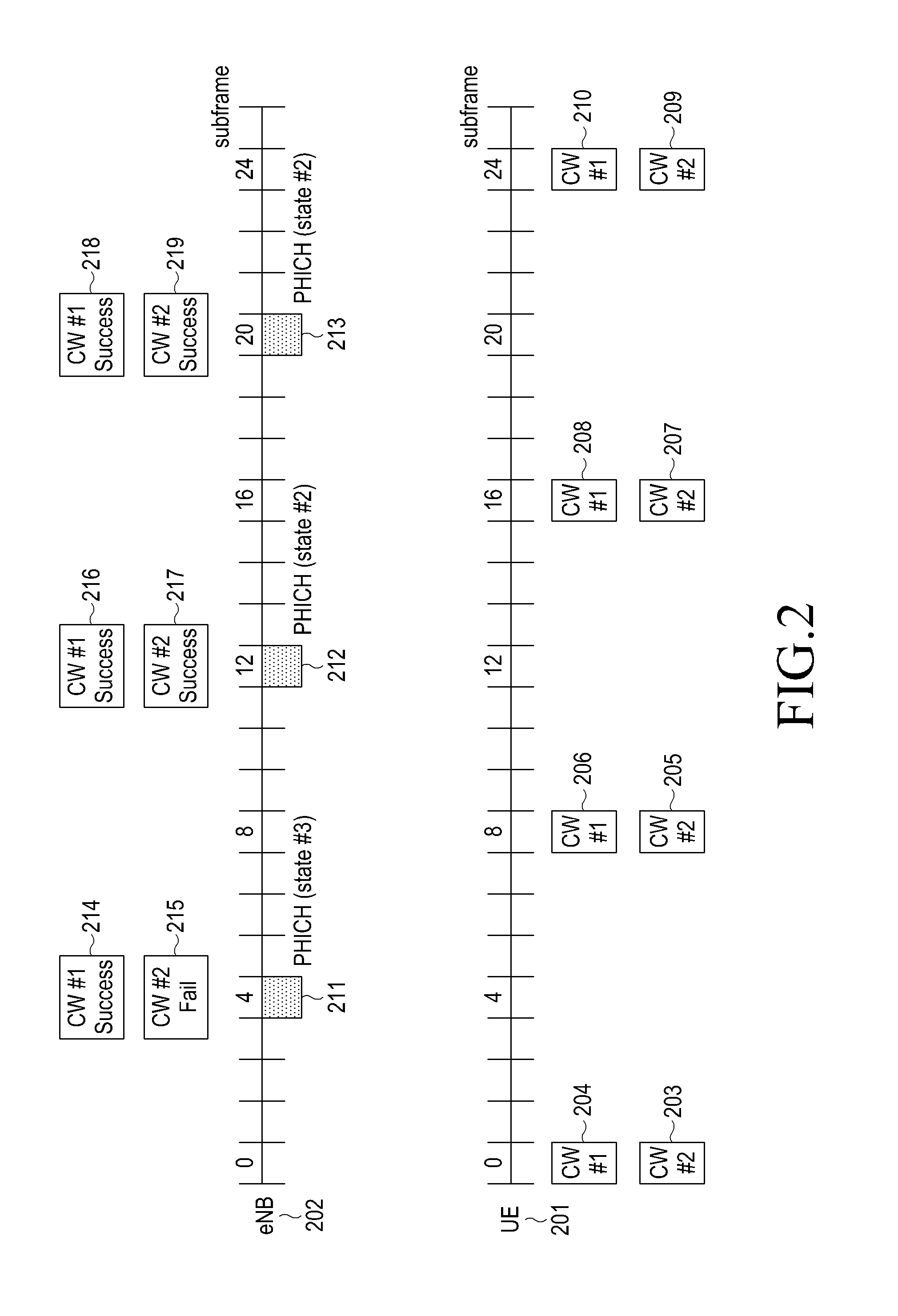
[0102]An eNB 202 provides new grant information to a UE 201 through a PDCCH in step 402. Upon receiving the PDCCH transmitted by the eNB 202, the UE 201 transmits a CW #1 and a CW #2 to the eNB 202, and the eNB 202 receives the CW #1 and the CW #2 from the UE 201 in step 403. Because the UE 201 may transmit only CW #1 or CW #2 according to the PDCCH information, the eNB 202 may also receive only CW #1 or CW #2. The eNB 202 decodes the CW #1 and the CW #2 in step 404. The eNB 202 selects one of state #1 to state #8 defined in Table 3 and configured to include a combination of the decoding results (ACK and NACK) of the CW #1 and the CW #2, Stop, and Continue. Upon selecting state #...

second embodiment

[0104]FIG. 5 illustrates a control information transmission method in an eNB according to the present invention, in which an eNB operation associated with the 7 states defined in Table 4 is shown.

[0105]Referring to FIG. 5, an eNB 202 provides new grant information to a UE 201 through a PDCCH in step 502. Because the UE 201 transmits a CW #1 and a CW #2 to the eNB 202 upon receiving the PDCCH, the eNB 202 receives the CW #1 and the CW #2 from the UE 201 in step 503. The UE 201 may transmit only CW #1 or CW #2 according to the PDCCH information, so the eNB 202 may also receive only CW #1 or CW #2. The eNB 202 decodes the CW #1 and the CW #2 in step 504. The eNB 202 selects one of state #1 to state #7 defined in Table 4 and configured to include a combination of the decoding results (ACK and NACK) of the CW #1 and the CW #2, Stop, and Continue.

[0106]Upon selecting state #1 in step 505, the eNB 202 transmits the state #1 over a PHICH in step 509. Upon selecting state #2 in step 506, the...

third embodiment

[0108]FIG. 6 illustrates a control information transmission method in an eNB according to the present invention, in which an eNB operation associated with the 5 states as defined in Table 5 is illustrated.

[0109]Referring to FIG. 6, an eNB 202 provides new grant information to a UE 201 through a PDCCH in step 602. Because the UE 201 transmits a CW #1 and a CW #2 to the eNB 202 upon receiving the PDCCH, the eNB 202 receives the CW #1 and the CW #2 from the UE 201 in step 603. The UE 201 may transmit only CW #1 or CW #2 according to the PDCCH information, so the eNB 202 may also receive only CW #1 or CW #2.

[0110]The eNB 202 decodes the CW #1 and the CW #2 in step 604. The eNB 202 selects one of state #1 to state #5 defined in Table 5 and configured to include a combination of the decoding results (ACK and NACK) of the CW #1 and the CW #2, Stop, and Continue.

[0111]Upon selecting state #1 in step 605, the eNB 202 transmits the state #1 over a PHICH in step 609. Upon selecting state #2 in...


PUM


Abstract

A method and apparatus for transmitting control information by an enhanced Node B (eNB) in a wireless communication system supporting Multiple-Input Multiple-Output (MIMO) technology is provided, in which at least one parameter required for initial transmission of User Equipment (UE) is transmitted through a Packet Data Control Channel (PDCCH), at least two codewords are received from the UE and then decoded, one of a plurality of indicators, related to an operation of the UE, is determined based on decoding results of at least two codewords, the determined indicator is transmitted through a Physical Hybrid ARQ indicator channel (PHICH), and at least one codeword is received that the UE generates and transmits based on the parameter required for initial transmission of the UE and the indicator related to the operation of the UE.

Description

PRIORITY[0001]This application claims priority under 35 U.S.C. §119(a) to an application filed in the Korean Intellectual Property Office on Mar. 29, 2010 and assigned Serial No. 10-2010-0028205, the entire disclosure of which is incorporated herein by reference.BACKGROUND OF THE INVENTION[0002]1. Field of the Invention[0003]The present invention relates generally to a method and apparatus for transmitting and receiving control information in a multi-antenna system or a Multiple-Input Multiple-Output (MIMO) system, and more particularly, to a method and apparatus in which an enhanced Node B (eNB) informs User Equipment (UE) of the success or failure in decoding received uplink data.[0004]2. Description of the Related Art[0005]A MIMO technique, which is a multi-antenna technique that has evolved from the existing Single-Input Single-Output (SISO) technique using a single transmit antenna and a single receive antenna, adopts multiple transmit antennas and multiple receive antennas to ...

Claims


Application Information

Patent Timeline
Patent Type & Authority Patents(United States)
IPC IPC(8): H04W4/00
CPCH04L1/1671H04L1/1864
Inventor YEON, MYUNG-HOONKIM, YOUN-SUNHAN, JIN-KYU
Owner SAMSUNG ELECTRONICS CO LTD
Why Eureka
Try Eureka