Rotary vibration damper with centrifugal force pendulum

a technology of centrifugal force and rotary, which is applied in the direction of fluid gearings, couplings, belts/chains/gearings, etc., can solve the problems of large assembly capability demands of rotary components, and achieve the effect of simple assembly and easy rigging

Active Publication Date: 2014-06-03
SCHAEFFLER TECH AG & CO KG
View PDF6 Cites 5 Cited by
  • Summary
  • Abstract
  • Description
  • Claims
  • Application Information

AI Technical Summary

Benefits of technology

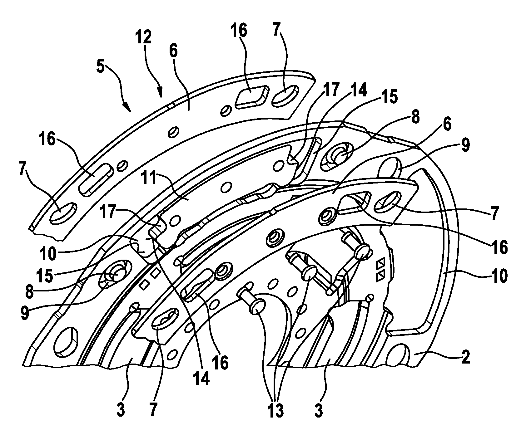
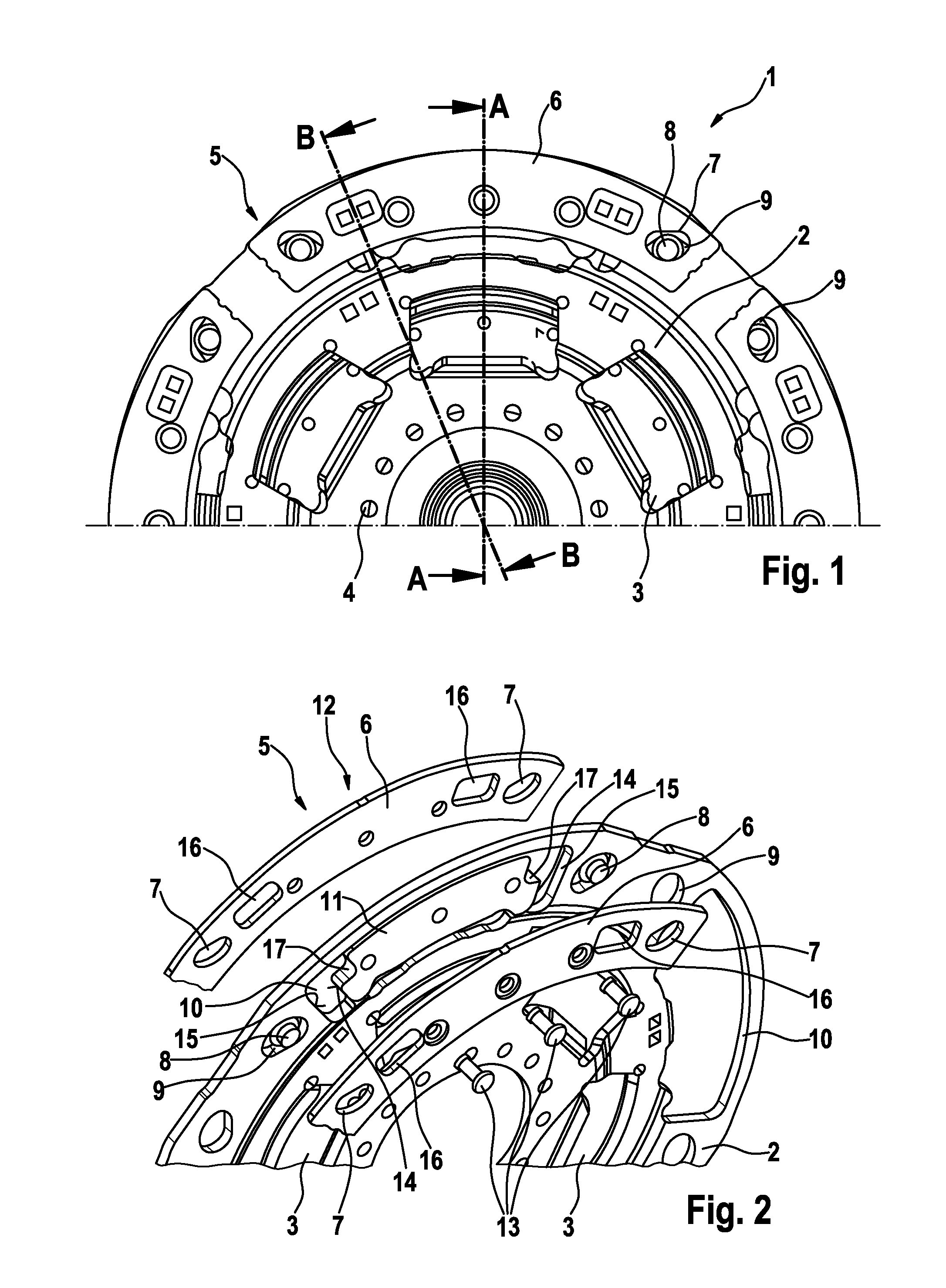
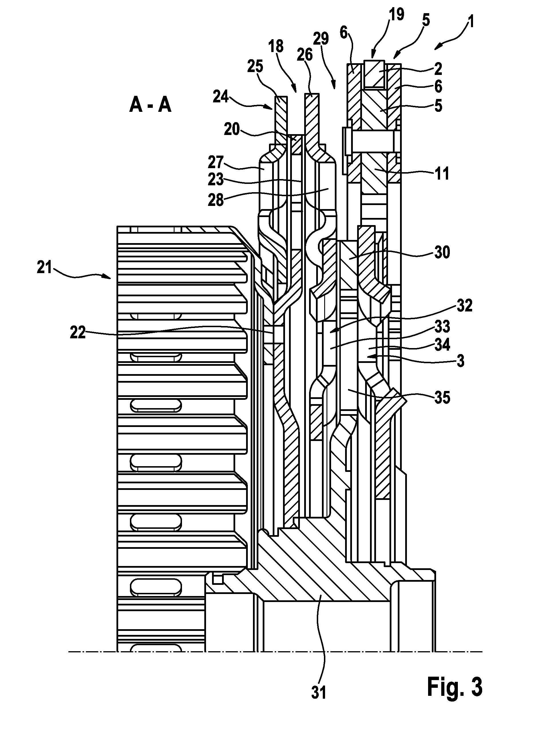
[0010]The recesses for auxiliary mass parts can be disposed between the raceways provided in the flange part for swivel-capable reception of both mass parts and the auxiliary mass part on the flange part. Swiveling or twisting of the mass parts against the flange part is limitedly stopped by the auxiliary mass parts contacting the flange part. In this regard, the auxiliary mass parts can get in contact with the front-side surfaces of the flange part before movement of mass parts inside the raceways and of the rolling bodies. The flange part is limited by the raceways. Thus, premature wear or defect of the parts can be avoided.
[0012]For example, for assembly reasons, at least one of the mass units including both axially opposite mass parts and the auxiliary mass part, for example, two displaced relative to each other in circumferential direction, can feature axially aligned cutouts. In this manner, punch-through through the flange part can be provided at centrifugal force pendulum height. This can serve for the assembly of further parts in the axial surrounding of arranged components of the rotary vibration damper or adjacent components of the drive train on this or other axially congested components. In this way, it is possible to rivet easily on the radius of the centrifugal force pendulum, in that one rivet through the punch-through or an abutment for riveting can be provided through the punch-through. Therefore, the use of auxiliary mass parts is advantageous because the mass lost through the cutout can be compensated or overcompensated in mass parts. Thus, in its size, the cutouts can be adapted to the tools required for assembly. The cutouts are provided as openings in the mass parts. These can also be edge cutouts, for example, in the auxiliary mass parts.

Problems solved by technology

Furthermore, through congested installation conditions, for example, in the installation space of hydrodynamic torque converters, and dual mass flywheels, great demands are made on the assembly capability of components of the rotary vibration damper.

Method used


Image

  • Rotary vibration damper with centrifugal force pendulum
  • Rotary vibration damper with centrifugal force pendulum
  • Rotary vibration damper with centrifugal force pendulum

Examples


Embodiment Construction

[0021]At the outset, it should be appreciated that like drawing numbers on different drawing views identify identical, or functionally similar, structural elements of the invention. While the present invention is described with respect to what is presently considered to be the preferred aspects, it is to be understood that the invention as claimed is not limited to the disclosed aspects.

[0022]Furthermore, it is understood that this invention is not limited to the particular methodology, materials and modifications described and, as such, may, of course, vary. It is also understood that the terminology used herein is for the purpose of describing particular aspects only, and is not intended to limit the scope of the present invention, which is limited only by the appended claims.

[0023]Unless defined otherwise, all technical and scientific terms used herein have the same meaning as commonly understood to one of ordinary skill in the art to which this invention belongs.

[0024]FIG. 1 sho...


PUM


Abstract

A rotary vibration damper with an input part and an output part having a centrifugal force pendulum disposed on a flange part of the input part or output part, with several mass parts distributed over the circumference of the flange part, and disposed on two sides of the flange part, in raceways of the flange part, and limitedly displaceable in the circumferential direction, and in the radial direction by which two mass parts are interconnected respectively on opposite sides of the flange part.

Description

CROSS-REFERENCE TO RELATED APPLICATIONS[0001]This application is the National Stage of PCT International Application No. PCT / DE2009 / 000702, filed May 14, 2009, which application published in German and is hereby incorporated by reference in its entirety, which application claims priority from German Patent Application No. DE 10 2008 026 271.4, filed Jun. 2, 2008, which is incorporated by reference in its entirety.FIELD OF THE INVENTION[0002]The invention relates to a rotary vibration damper with a centrifugal force pendulum in which the centrifugal force pendulum is integrated in a flange part of the rotary vibration damper.BACKGROUND OF THE INVENTION[0003]Rotary vibration dampers feature a centrifugal force pendulum for improving compensation of rotary vibration, particularly introduced into a drive train of a motor vehicle by an internal combustion engine. Such a centrifugal force pendulum can be integrated in an input part or an output part of the rotary vibration damper, in that...

Claims


Application Information

Patent Timeline
Patent Type & Authority Patents(United States)
IPC IPC(8): F16F15/131
CPCF16F15/13128F16H2045/0263F16H2045/0231F16H45/02F16F15/145Y10T74/2128
Inventor HUEGEL, CHRISTIANDINGER, CHRISTIAN
Owner SCHAEFFLER TECH AG & CO KG
Why Eureka
Try Eureka