

Venting valve
a technology of venting valve and valve body, which is applied in the direction of valve details, functional valve types, check valves, etc., can solve the problems of large mounting space, high assembly expenditure, and inability to meet the sealing function to a satisfactory degree, and achieve the effect of simple manufactur
- Summary
- Abstract
- Description
- Claims
- Application Information
AI Technical Summary
Benefits of technology
Problems solved by technology
Method used
Image

Examples
Embodiment Construction
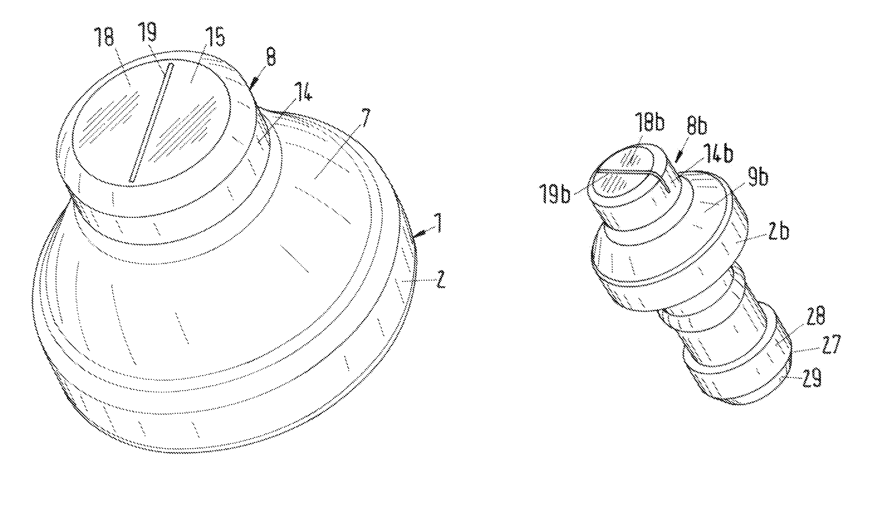
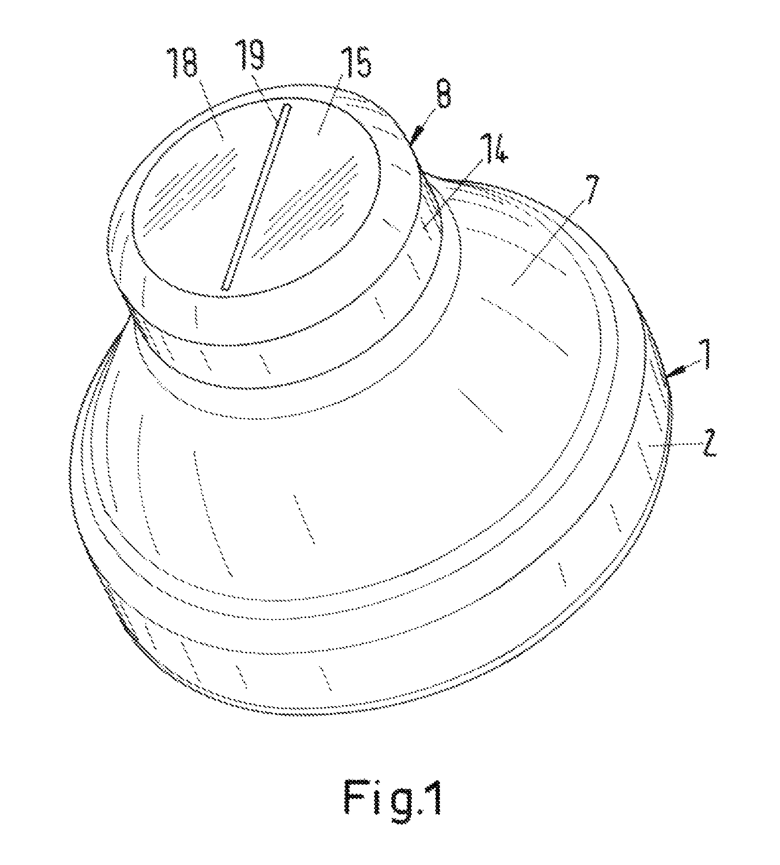
[0024]The venting valves disclosed in the following are comprised of elastomer material and are embodied in a cap shape. With the venting valves different apparatus, for example, motor, axle, or transmission housings, are sealed. In the embodiment, the venting valves are designed such that a sealing function below 0.1 bar overpressure within the apparatus is realized by them, above 0.1 bar however they will open. These pressure values are to be understood as exemplary only. The differential pressure can be also higher or lower, depending on the slot configuration, for example.
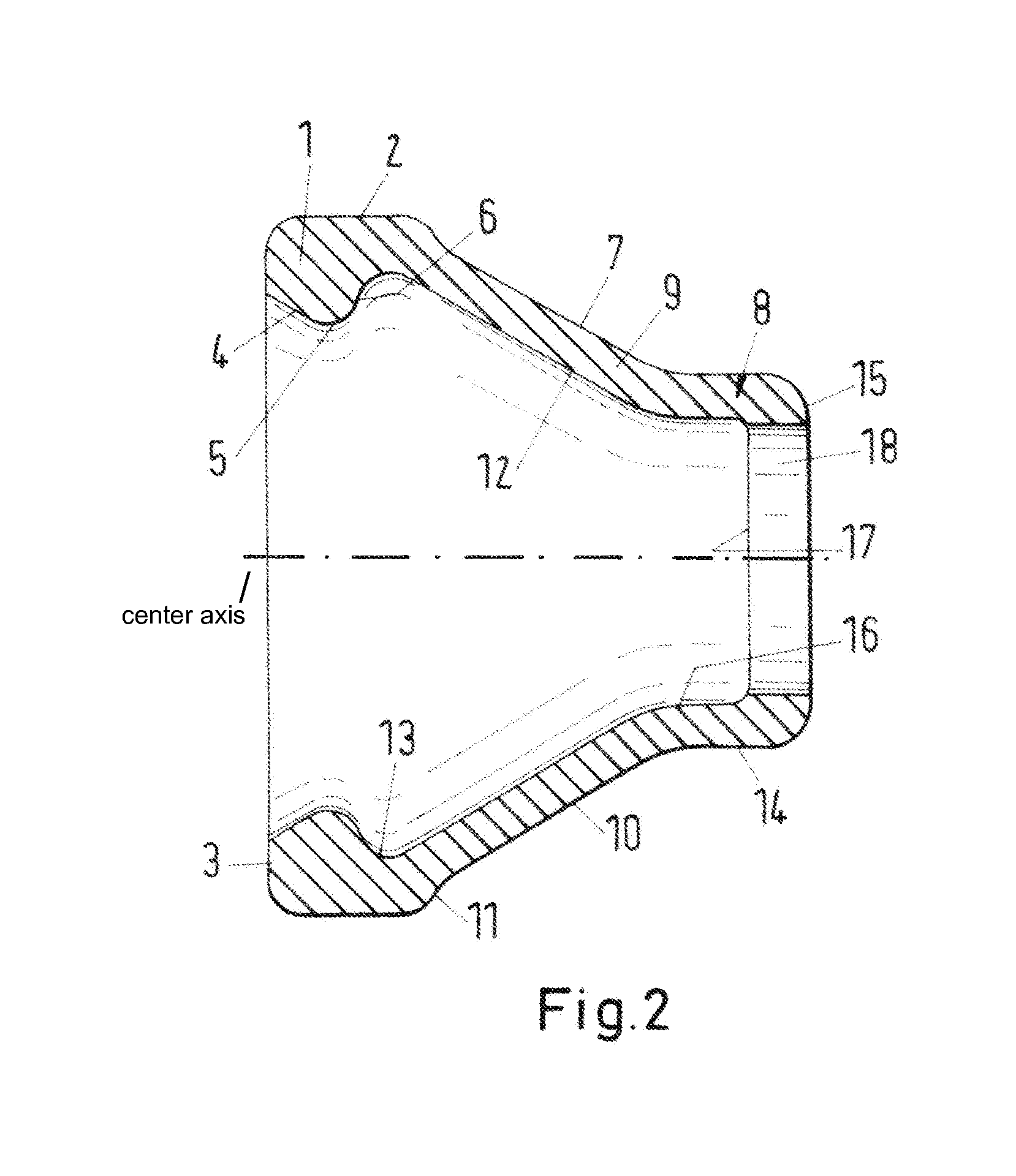
[0025]The venting valve according to FIGS. 1 and 2 has a circular cross-section and is provided with a cylindrical securing part 1 with which the venting valve is attached to an appropriate connector of the apparatus. The securing part 1 has a cylindrical outer wall 2 that passes into a flat end face 3. It passes at an obtuse angle into a conical surface 4 that tapers inwardly. The conical surface 4 passes at a...
PUM
 Abstract
Description
Claims
Application Information