Steam turbine

a steam turbine and steam technology, applied in the field of steam turbines, can solve the problems of high temperature occurring during the operation of steam turbines, metal paneling being destroyed, coating melting, etc., and achieve the effect of preventing the destruction of metal paneling and minimizing the loss of eddy curren

Active Publication Date: 2014-06-10
SIEMENS ENERGY GLOBAL GMBH & CO KG
View PDF13 Cites 2 Cited by
  • Summary
  • Abstract
  • Description
  • Claims
  • Application Information

AI Technical Summary

Benefits of technology

[0005]Metal paneling is attached in the area of the magnetic bearing to minimize the eddy current losses in the bearing. This metal paneling normally consists of a number of metal rings insulated from one another by a suitable coating. The high temperatures in the shaft of a steam turbine can lead to the coating melting and thereby to the metal paneling being destroyed.
[0006]An object of the present invention is thus to specify a steam turbine with at least one magnetic bearing for the shaft with which overheating of the magnetic bearing and thus destruction of the metal paneling is prevented.
[0008]The explicit cooling of the magnetic bearing, specifically of a magnetic bearing arranged at the hot end of a steam turbine, prevents overheating of the insulating layers of the metal paneling and thereby destruction of the magnetic bearing.

Problems solved by technology

If a magnetic bearing is used to support the shaft of a steam turbine, then the high temperatures occurring during the operation of the steam turbine are a problem for the magnetic bearing.
The high temperatures in the shaft of a steam turbine can lead to the coating melting and thereby to the metal paneling being destroyed.

Method used


Image

  • Steam turbine
  • Steam turbine
  • Steam turbine

Examples


Embodiment Construction

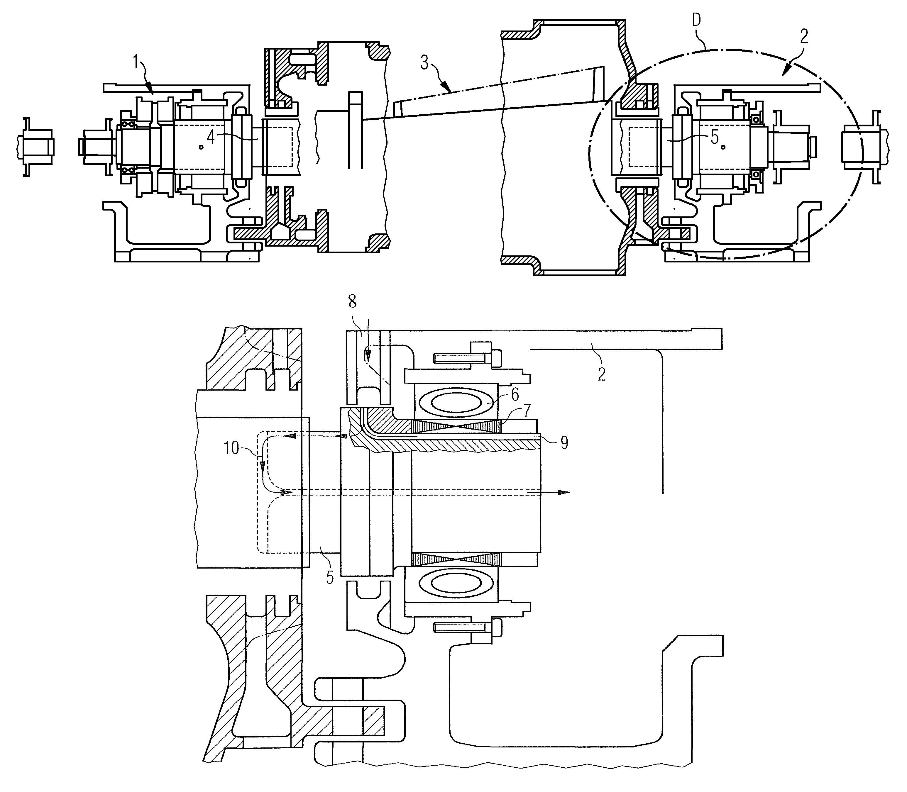
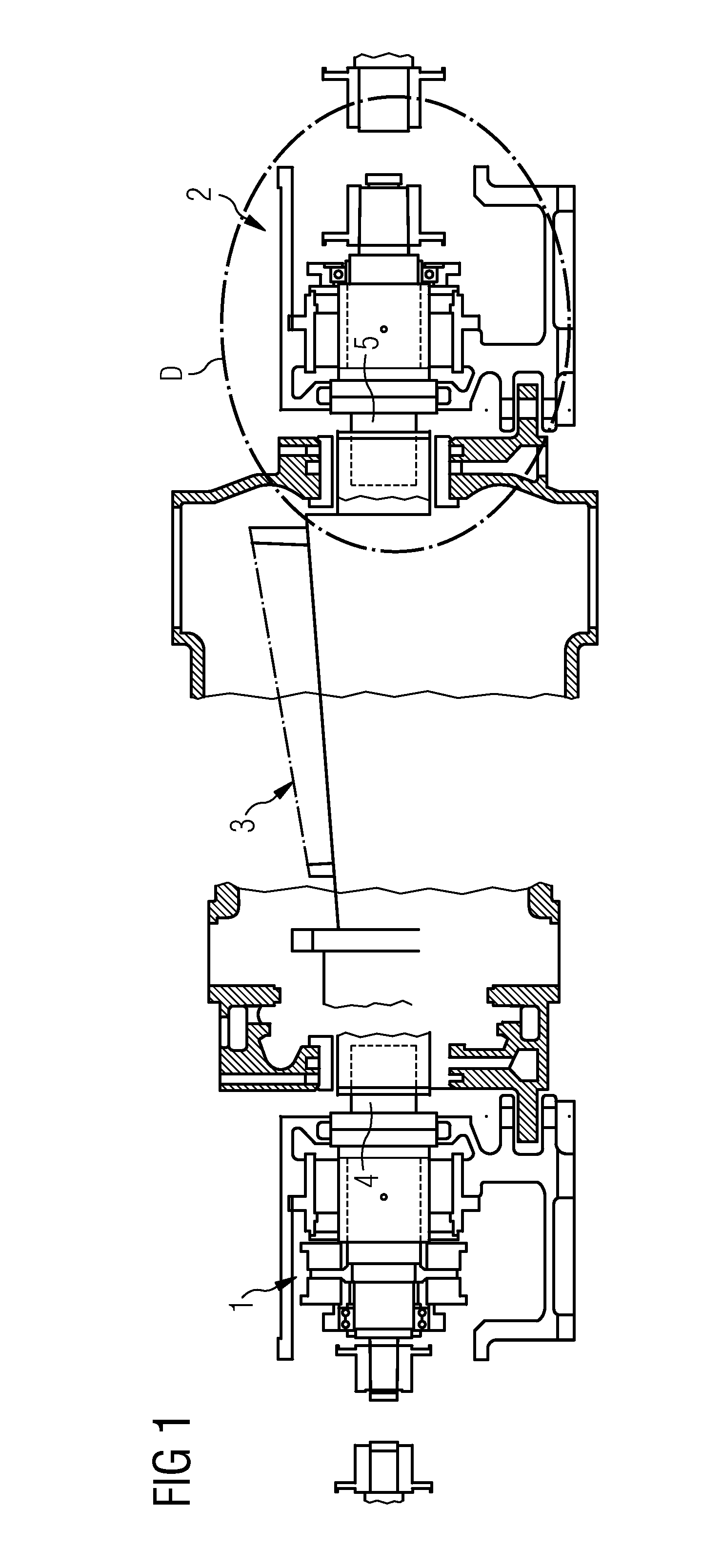
[0016]FIG. 1 shows the modules of an inventive steam turbine needed to understand the invention. The steam turbine essentially consists of the front bearing housing 1, the rear bearing housing 2 which is located at the hot end of the steam turbine, and the center area 3 with the blading.

[0017]The shaft of the steam turbine is supported in the front bearing housing 1 by a front screwed-on shaft end 4 and in the rear bearing housing 2 by a rear screwed-on shaft end 5.

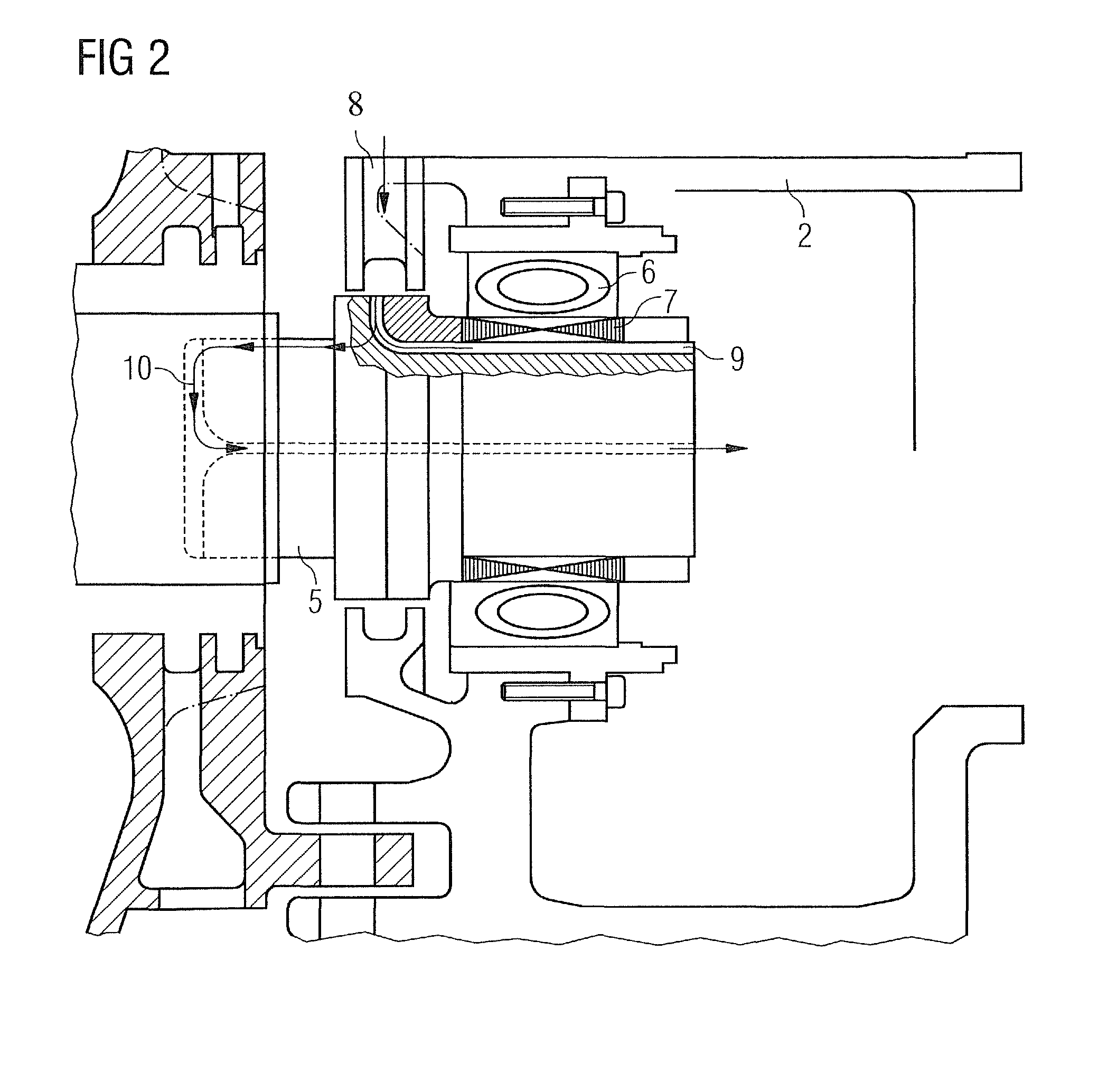
[0018]FIG. 2 shows the section D through FIG. 1, i.e. FIG. 2 shows the rear bearing housing 2 in detail. The magnetic bearing 6 with the metal paneling 7 is located in the rear bearing housing 2. Arranged below the lamination are cooling air ducts 9. The cooling air is supplied via a cooling air supply duct 8 to these cooling air ducts 9 which are arranged in a helical structure underneath the magnetic bearing 6.

[0019]The individual cooling air ducts 9 end at the free end of the rear screwed-on shaft end 5 in the rear bea...


PUM


Abstract

A steam turbine with at least one magnetic bearing for the shaft is provided, a metal paneling being attached in the area of a magnetic bearing. The metal paneling consists of metal rings insulated from one another. Further, cooling air ducts are provided in the area of the magnetic bearing.

Description

CROSS REFERENCE TO RELATED APPLICATIONS[0001]This application claims priority of European Patent Office Application No. 08016914.7 EP filed Sep. 25, 2009, which is incorporated by reference herein in its entirety.FIELD OF INVENTION[0002]The present invention relates to a steam turbine with at least one magnetic bearing for the shaft, with steel paneling being attached in the area of a magnetic bearing.SUMMARY OF INVENTION[0003]A magnetic bearing represents an alternate option to the support methods used to date. The outstanding attribute of the magnetic bearing is the lack of contact between supported part and bearing. The bearing forces needed are generated by an appropriate magnetic field which is established between the fixed part and the part to be supported. This means that the magnetic bearing is friction-free and needs no lubricant.[0004]If a magnetic bearing is used to support the shaft of a steam turbine, then the high temperatures occurring during the operation of the stea...

Claims


Application Information

Patent Timeline
Patent Type & Authority Patents(United States)
IPC IPC(8): F01D5/08
CPCF16C37/005F16C32/0468F01D25/125F16C2360/23F16C32/048F05D2240/51F16C2360/00
Inventor KUHN, HELMUT
Owner SIEMENS ENERGY GLOBAL GMBH & CO KG
Why Eureka
Try Eureka