Reciprocating motor

Inactive Publication Date: 2005-05-31
LG ELECTRONICS INC
View PDF9 Cites 0 Cited by
  • Summary
  • Abstract
  • Description
  • Claims
  • Application Information

AI Technical Summary

Benefits of technology

[0017]Therefore, it is an object of the present invention to provide a reciprocating motor, capable of minimizing eddy current loss which is generated in a magnet frame, in driving a motor.
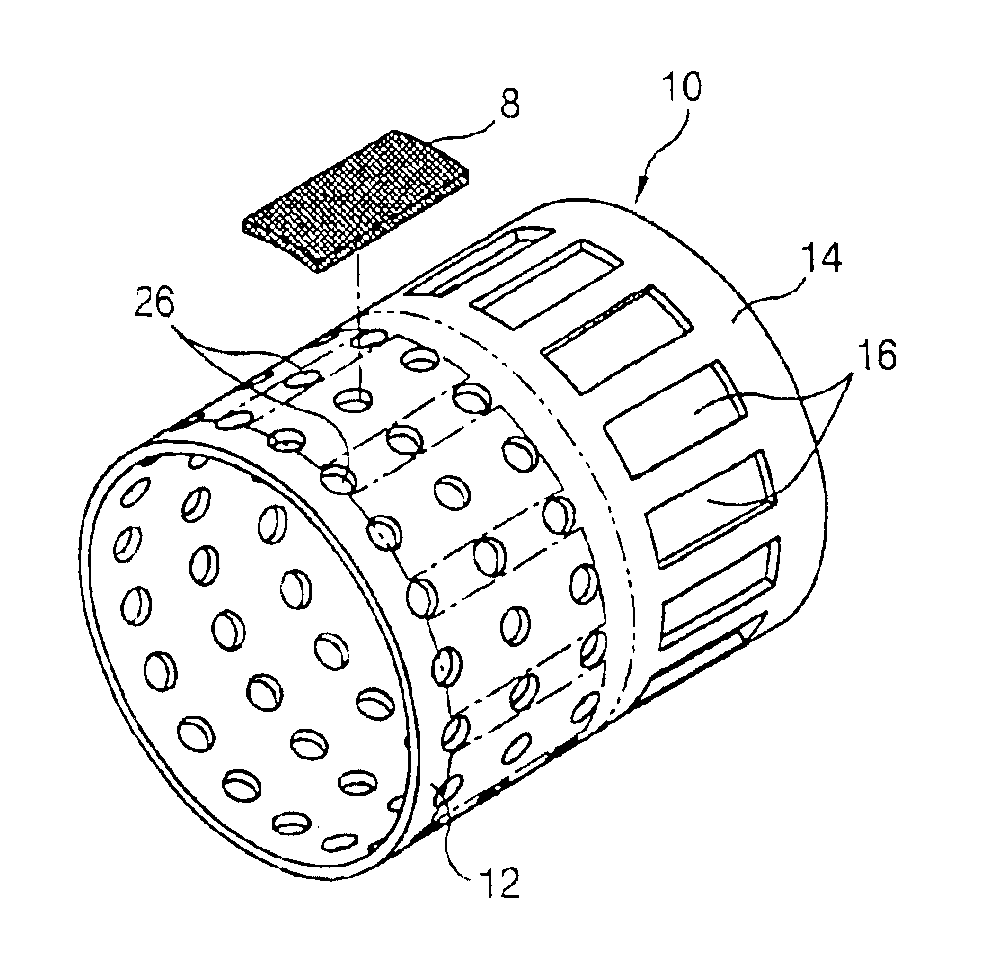
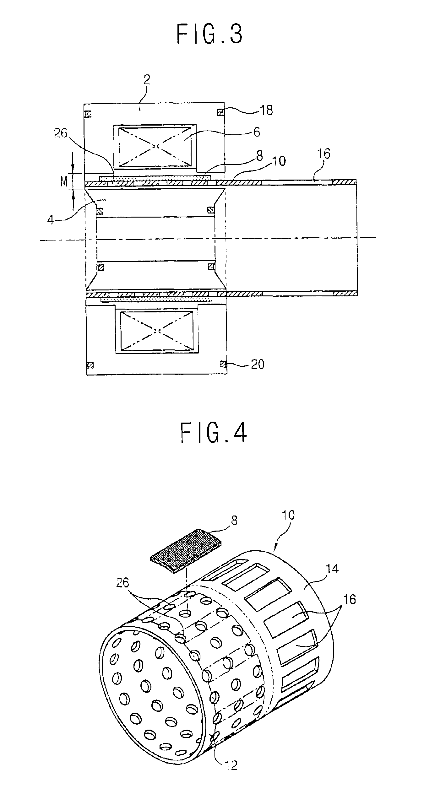
[0018]A second object of the present invention is to provide a reciprocating motor, capable of preventing deformation of the magnet frame in shaping an eddy current preventing hole by improving the structure of the eddy current preventing hole which is formed in the magnetic frame, to attenuate the eddy current loss and maintaining roundness of the magnetic frame.
[0019]A third object of the present invention is to provide a reciprocating motor formed in a structure that the eddy current preventing hole, which is formed in the magnetic frame can strengthen the magnetic frame, capable of preventing damage of the magnetic frame caused from a load applied to the magnetic frame by the reciprocating movement of the magnet in driving the motor.
[0020]A fourth object of the present invention is to provide a reciprocating motor, capable of preventing damage of shaping instrument and reduce manufacturing cost, by improving a method for forming the eddy current preventing hole in the magnetic frame.

Problems solved by technology

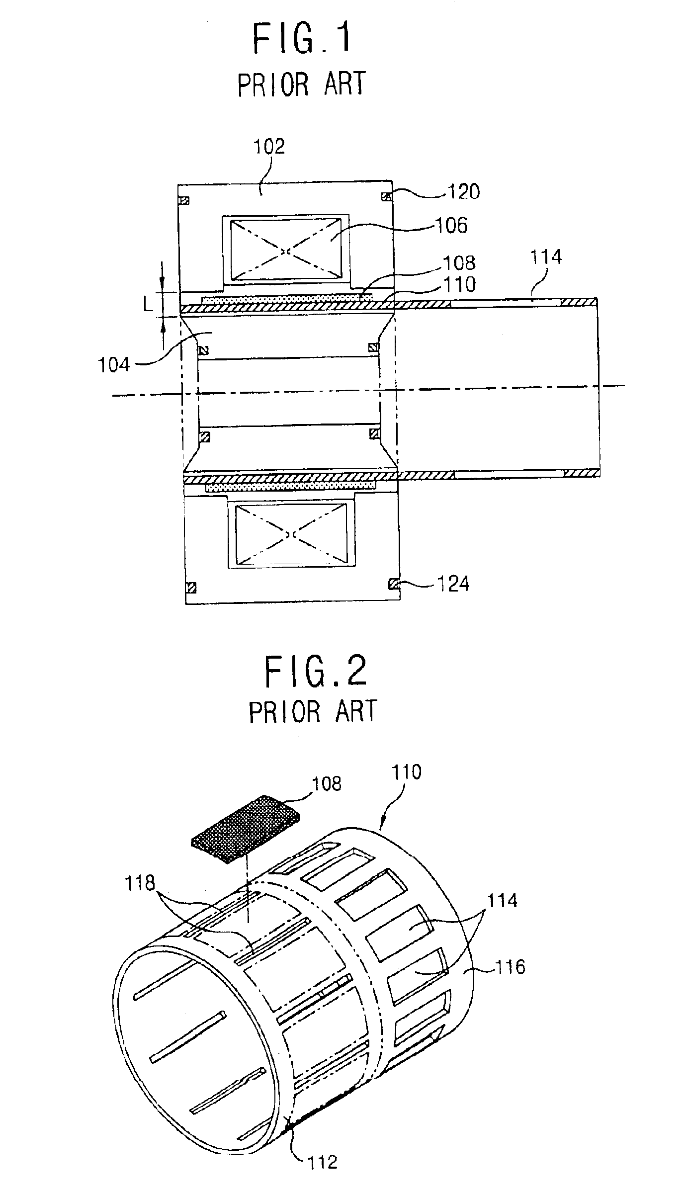
However, in the conventional reciprocating motor, the slit formed to attenuate eddy current loss generated in driving the motor, is formed in the shape of a stripe having a narrow width and accordingly, there occurs a problem that molding accuracy is lowered since the slit is deformed by the compressing stress generated in the circumferential direction of the magnet frame in the molding operation, and it is difficult to maintain roundness of the magnet frame.
Also, when the magnet performs a linear reciprocating movement, a force is applied to the magnet frame in the direction of the length by inertia of the magnet and an edge crack is generated in an edge portion of the slit by the force applied to the magnet frame.
Since the width of the slit is narrow and thin, and the width of the punch for the punching operation is also narrow and the thickness of the punch is thin, there occurs a problem that the punch and die are damaged in the processing.

Method used


Image

  • Reciprocating motor
  • Reciprocating motor
  • Reciprocating motor

Examples


second embodiment

[0047]As shown in FIG. 5, the eddy current preventing hole which is formed in the magnet frame in accordance with the second embodiment is formed as a circular through hole 28 having a predetermined diameter and positioned in a random shape.

[0048]As shown in FIG. 6, as the eddy current preventing hole, a plurality of circular through holes 30 can be positioned to be a predetermined angle sloped in the direction of snaft of the magnet frame 10. As shown in FIG. 7, the number of the circular through holes 32 having a predetermined diameter can be changed according to the position where the through holes are formed in the direction of shaft of the magnet frame 10.

third embodiment

[0049]As shown in FIG. 8, the eddy current preventing hole which is formed in the magnet frame 10 in accordance with the third embodiment is formed in a shape of a square through hole 34 having a predetermined size and a predetermined number of the holes are formed in the directions of the shaft and circumference of the magnet frame 10.

[0050]As shown in FIG. 9, the eddy current preventing hole in accordance with the third embodiment can be formed as square through holes 36 which are positioned in two rows in the direction of circumference of the magnet frame. As shown in FIG. 10, the eddy current preventing hole can be formed in the shape of square through holes 38 which are positioned in a row at a uniform interval in the direction of circumference of the magnet frame 10.

fourth embodiment

[0051]As shown in FIG. 11, the eddy current preventing hole in accordance with the fourth embodiment is protruded and formed in the magnet mounting portion 12 in the shape of a cross-shaped through hole 40.


PUM


Abstract

A reciprocating motor in which a plurality of eddy current preventing holes (26) are formed in the directions of circumference and shaft of a magnet frame (10) in a magnet mounting portion (12) of the magnet frame (10)connected between the magnet (8)and component part which will perform a reciprocating movement, for transmitting a reciprocating movement of the magnet (8) to a component part, to prevent deformation of the magnet frame (10)in molding the eddy current (26) and maintain roundness of the magnet frame precisely by improving the structure of the eddy current preventing holes which are molded in the magnet frame.

Description

TECHNICAL FIELD[0001]The present invention relates to a reciprocating motor and particularly, to a reciprocating motor, capable of minimizing eddy current loss which is generated in driving a motor and lengthening life span of the motor.BACKGROUND ART[0002]In general, a motor is divided to a rotary motor for changing electric energy into rotary movement, reciprocating motor which changes electric energy into linear reciprocating movement, and the like.[0003]Particularly, in the reciprocating motor an outer stator and inner stator are positioned a predetermined interval apart from each other and a rotor having a magnet between the outer and inner stators. When a power is applied to a coil which is wound on the stator, the rotor preforms a linear reciprocating movement by interaction between the stator and magnet. The reciprocating motor is commonly used for a reciprocating compressor.[0004]FIG. 1 is a cross-sectional view showing a conventional reciprocating motor.[0005]The conventio...

Claims


Application Information

Patent Timeline
IPC IPC(8): H02K1/06H02K1/27H02K33/00H02K1/34H02K33/16H02K41/02
CPCH02K33/16H02K1/34H02K41/02
Inventor JUNG, WON-HYUNKU, BON-CHEOL
Owner LG ELECTRONICS INC
Why Eureka
Try Eureka