
Concentrated winding stator construction for high efficiency machine

a technology of winding stator and high efficiency machine, which is applied in the direction of windings, magnetic circuit shapes/forms/construction, windings, etc., can solve the problems of not achieving the high yield or packing density in manufacturing, the wire size may need to get quite large, and the wire may get larger. , to achieve the effect of reducing the loss of eddy current in the winding, good thermal solution and high current density

Active Publication Date: 2014-05-08
LC ADVANCED MOTOR TECH CORP
View PDF22 Cites 8 Cited by
  • Summary
  • Abstract
  • Description
  • Claims
  • Application Information

AI Technical Summary

Benefits of technology

The design of this patent improves the efficiency and power density of rotating machines by using innovative techniques such as edge form woundings, pre-insulated wire, and novel cooling manifold location. These techniques minimize eddy current losses and allow higher current density in the slot, resulting in higher overall power density of the rotating machine. The design also uses reliable and small metallic vessels for liquid cooling, which are brazed together into manifolds to efficiently direct the liquid to where the heat is generated. These approaches combine to create a reliable, small, efficient, and low cost design.

Problems solved by technology

Pre-insulated wire has been used with simple pin-bending solutions, but this would not achieve the higher packing density or high yields in manufacturing.
Further, in real applications, the wire size may need to get quite large to accommodate the correct number of turns.
This wire may get larger than commonly available for pre-insulated wire and this larger wire will have more eddy current losses in the wire due to slot leakage magnetic flux.

Method used


Image

  • Concentrated winding stator construction for high efficiency machine
  • Concentrated winding stator construction for high efficiency machine
  • Concentrated winding stator construction for high efficiency machine

Examples


Embodiment Construction

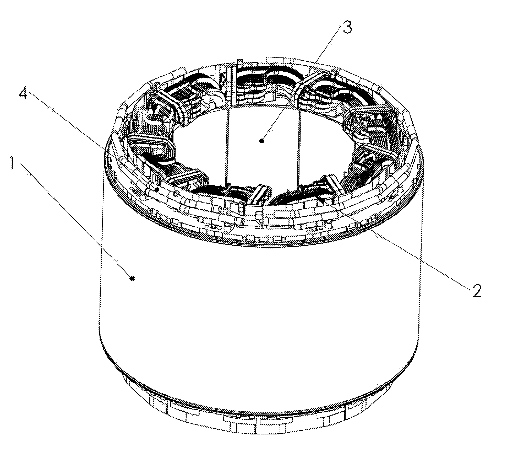
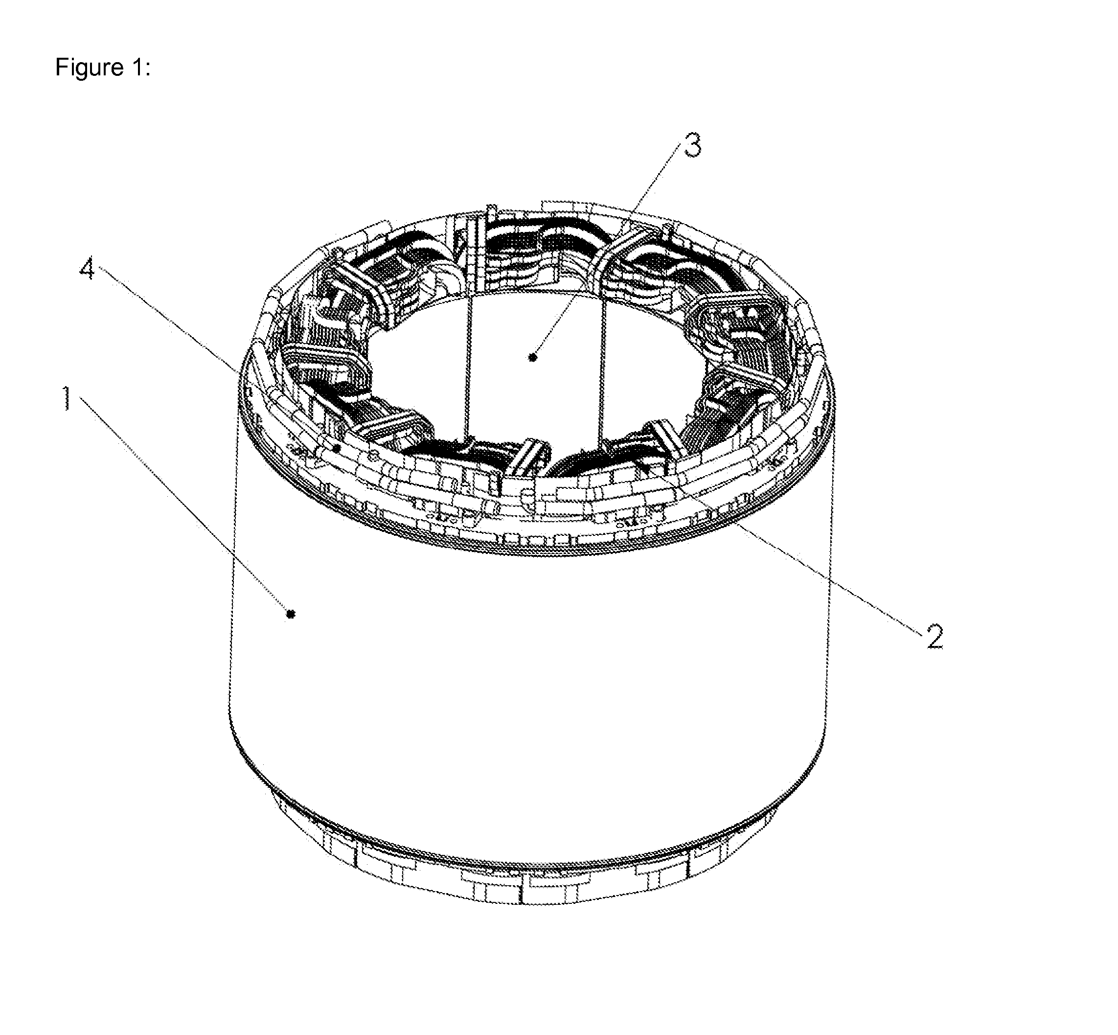
[0040]Referring particularly to FIG. 1, a stator assembly 1 is shown containing stator coils 2 and stator lamination teeth 3. Also shown is a fluid manifold 4 for supplying coolant to the motor or generator.

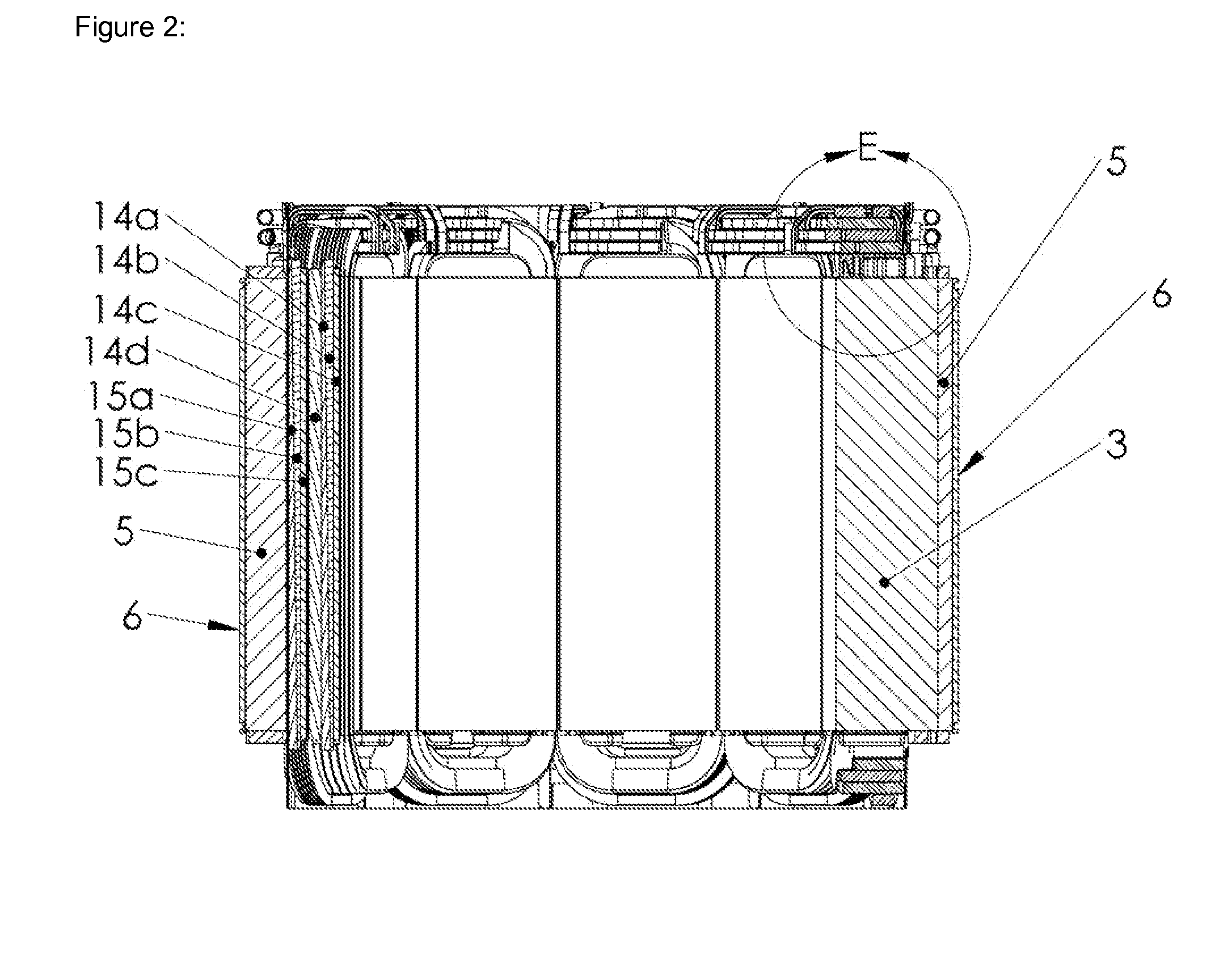
[0041]FIG. 2 shows more detail on the stator assembly showing outer tube 6, outer laminations 5, and stator teeth 3. The stator shown in FIG. 2 has a double layer concentrated winding since there is a winding around every stator tooth. In addition, the stator winding is comprised of four portions: innermost layer 8, second layer 9, third layer 10, and fourth layer 11 as shown in FIG. 3. The four portions are separate and distinct from this being a double layer winding which refers to there being a winding around every stator tooth.

[0042]Each winding surrounds a cooling manifold with the upper portion 7 shown in FIG. 3 and the in slot portion 12 shown in FIG. 5. The cooling manifold is shown with 8 holes in each side. Since this is an even number it facilitates a single sided mani...


PUM


Abstract

A permanent magnet motor, generator or the like that is constructed with a concentrated winding using a separate tooth. This tooth is preloaded in such a way to achieve high structural rigidity and good magnetic performance.

Description

BACKGROUND OF THE INVENTION[0001]Rotary electric machines including electric motors, generators, and the like have employed various types of stator windings. The most common stator winding type is a distributed winding. One type of which is an integer-slot winding wherein the number of slots per pole per phase is an integer. An example of this is a 4 pole 12 slot, 3 phase motor. The number of slots per pole per phase is 1 and therefore an integer. These windings typically require some relatively complex end turns to wire them properly.[0002]Another type of distributed winding is a fractional-slot winding. When the number of slots per pole per phase is a fraction greater than one, this is called a fractional-slot winding. This also has complicated end turns and has the disadvantage of being less efficient. It is sometimes used to smooth out torque ripple or for other specific applications.[0003]Another type of winding is a concentrated winding when the number of slots per pole per ph...

Claims


Application Information

Patent Timeline
Patent Type & Authority Applications(United States)
IPC IPC(8): H02K1/16H02K3/12
CPCH02K3/18H02K3/24H02K3/522H02K15/045H02K1/148H02K9/197
Inventor MARVIN, RUSSEL HUGHJOHNSON, THOMAS R.
Owner LC ADVANCED MOTOR TECH CORP
Learn More