Electromagnetic rotary drive and rotational device

a technology of rotary drive and rotor, which is applied in the direction of bearings, dynamo-electric machines, shafts, etc., can solve the problems of increased cost, significant contribution, and metals represent a substantial cost factor, so as to reduce the fluctuation of torque at least significantly, simplify the sensor system required for the control and regulation of the rotor position, and minimize the effect of eddy current loss

Active Publication Date: 2019-11-21
LEVITRONIX
View PDF0 Cites 15 Cited by
  • Summary
  • Abstract
  • Description
  • Claims
  • Application Information

AI Technical Summary

Benefits of technology

[0039]The sensor system required for the control and regulation of the rotor position can be simplified by the radially outwardly disposed ring, whether it is made of ferromagnetic material or of electrically conductive material, because the desired spacing of the rotor from the coil cores is a constant value viewed over the periphery of the rotor.
[0040]In order in particular to minimize eddy current losses in the stator, it is advantageous if each of the coil cores are each manufactured of sheet metal from elements, wherein the elements are stacked in the peripheral direction of the rotor.
[0041]A further advantageous measure is that the end faces of the transverse limbs of the coil cores facing the rotor have a height in the axial direction that is respectively larger than the axial height of the magnetically effective core of the rotor. A greater or better passively magnetic stabilization of the rotor with respect to tilts with respect to the desired axis of rotation in particular results from this. In addition, the higher end faces of the transverse limbs result in a concentration of the magnetic flux.
[0042]Preferably, the end faces of the transverse limbs of the coil cores facing the rotor are each curved as segments of a circular cylinder, which is coaxial with the rotor so that the rotor has a constant distance from the end face in a centered state in the radial direction viewed over the respective end face. On the one hand, the effective magnetic air gap between the stator and the rotor is kept as small as possible by this curved configuration of the end faces, which follows the curvature of the rotor. On the other hand, the torque exerted onto the rotor becomes especially constant viewed over the rotation of the rotor by the constant distance between the rotor and the end faces of the transverse limbs viewed over the periphery of the rotor, i.e. fluctuations of the torque are at least significantly reduced. This also significantly reduces torque triplets and detent torques.

Problems solved by technology

Such single-use applications today frequently replace processes in which all those components, which come into contact with the substances to be treated in the process previously had to be cleaned and sterilized in a complex manner, for example by steam sterilization, due to the very high purity demands.
However, such metals represent a substantial cost factor due to their comparatively small occurrence and due to their complex mining and processing.
In addition, the waste disposal of such permanent magnets after a single use, for example, is frequently also associated with problems or a high effort under technical environmental aspects, whereby additional costs arise.
This causes the transverse webs to saturate magnetically practically immediately in the operating state, i.e. they reach the range of saturation magnetization, so that they no longer make a significant contribution to magnetic flux conduction and thus change the magnetic anisotropy of the rotor only insignificantly.

Method used


Image

  • Electromagnetic rotary drive and rotational device
  • Electromagnetic rotary drive and rotational device
  • Electromagnetic rotary drive and rotational device

Examples


first embodiment

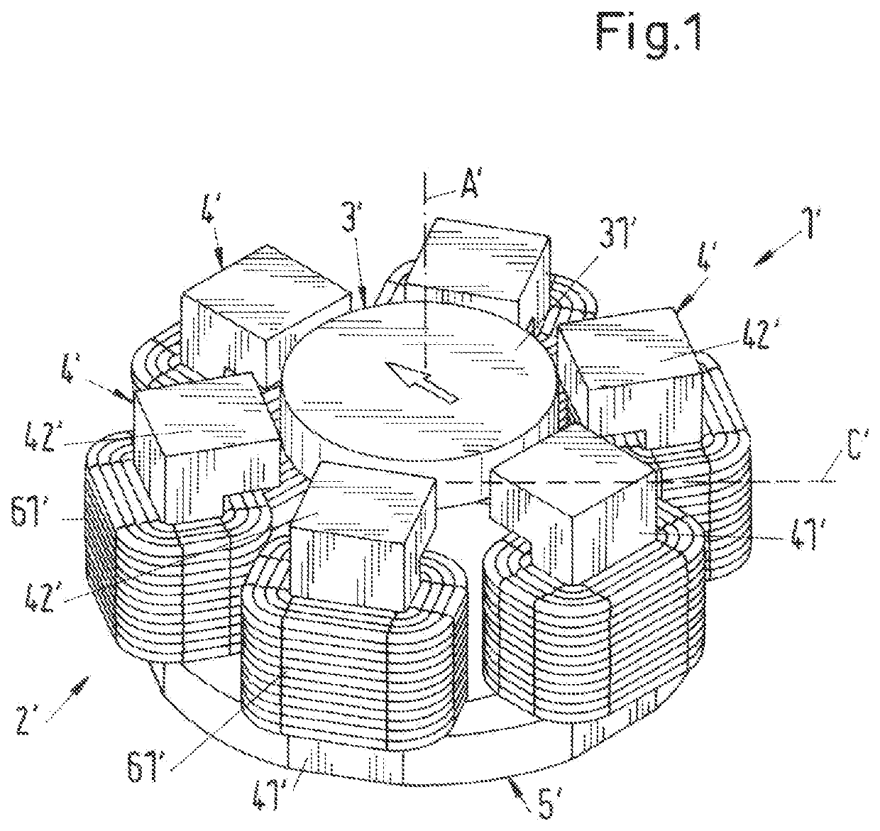
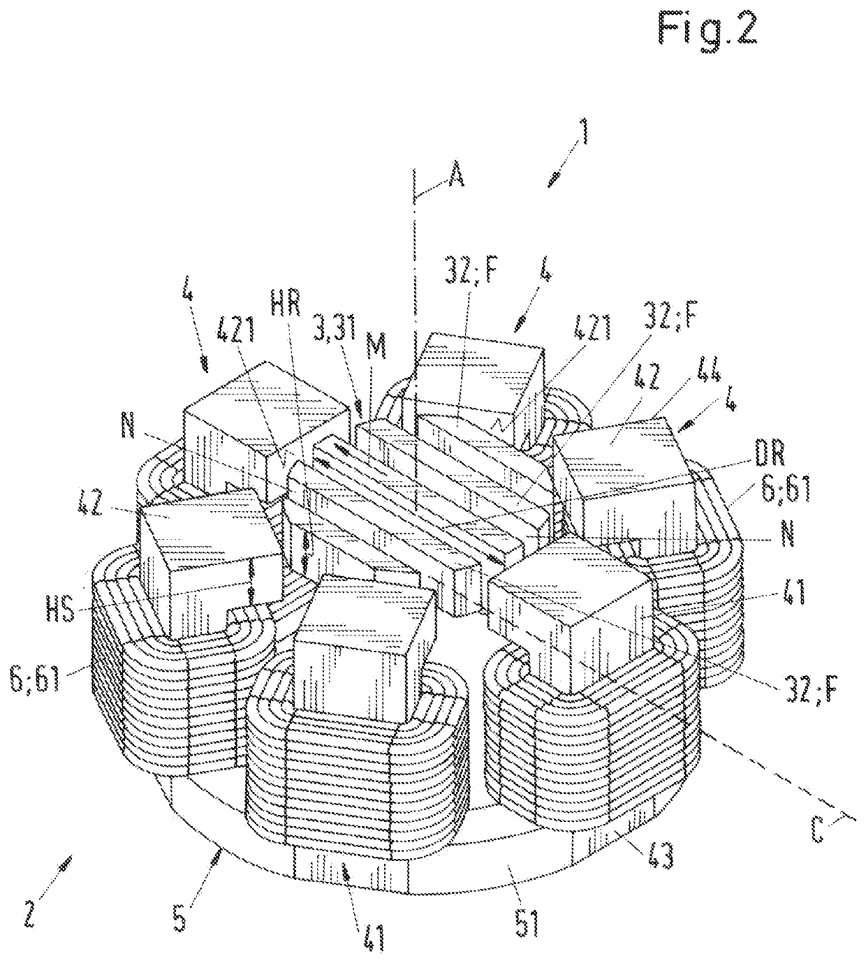
[0067]FIG. 2 shows a perspective representation of an electromagnetic rotary drive according to the invention, which is designated as a whole with the reference sign 1. The rotary drive 1 is configured as a temple motor and comprises a stator 2 and a rotor 3 being contactlessly magnetically levitated in the stator 2, which rotor is configured free of coils, free of a cage and free of permanent magnets. The stator 2 is also free of permanent magnets. The rotor 3 comprises a magnetically effective core 31, which is configured in the shape of a circular disk or of a circular cylinder of the height HR (see also FIG. 4) and with the diameter DR. The term “magnetically effective core 31” means that region of the rotor 3, which interacts with the stator 2 for the torque generation and for generating the magnetic levitation forces. In the operating state, the rotor 3 is contactlessly magnetically drivable about a desired axis of rotation by the stator 2. The desired axis of rotation refers ...

second embodiment

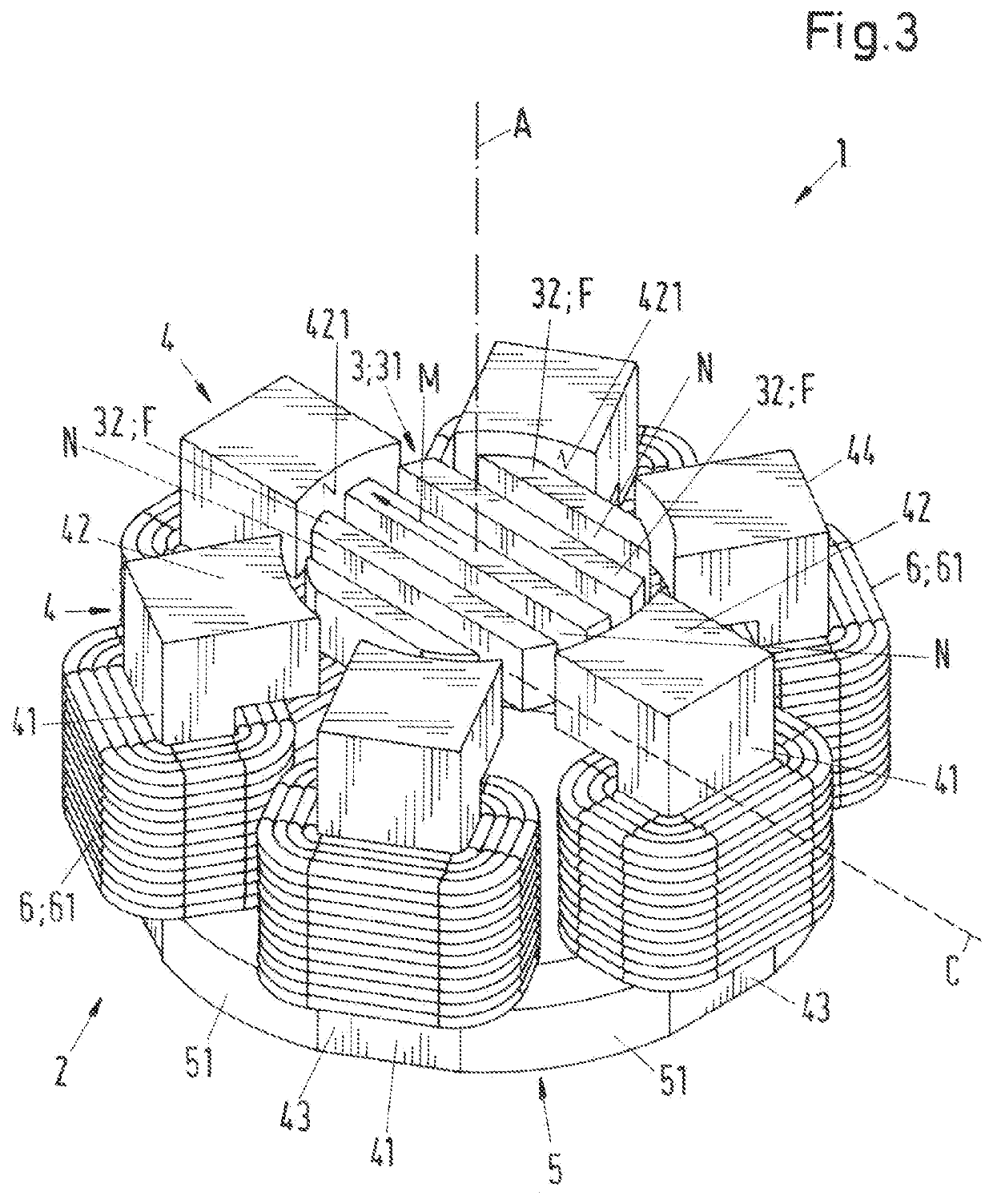
[0119]In the variant shown in FIG. 7 that corresponds to the coil core 4, which is shown in FIGS. 3 to 5 for the second embodiment, the end face 421 of the transverse limbs 42 of the coil cores 4 is curved as a segment of a circular cylinder, which is coaxial with the rotor 3. The radially outer boundary surface 49 of the coil core 4 is configured as planar surface, i.e. it is not curved.

[0120]In FIG. 7, the inner circle along which the end face 421 of the transverse limb 42 extends, is indicated by the circle having the reference sign SI. This circle SI is concentric with the disk-shaped magnetically effective core 31 of the rotor, i.e. the center of the circle SI lies on the desired axis of rotation of the rotor 3. Thus, the curvature of the end face 421 follows the curvature of the outer surface of the magnetically effective core 31 of the rotor 3.

[0121]For the production of the variant shown in FIG. 7, for example, the variant shown in FIG. 6 can be assumed. Then the planar end ...


PUM


Abstract

An electromagnetic rotary drive includes a rotor, a stator and windings. The rotor includes a magnetically effective core. The rotor is contactlessly magnetically drivable about an axis of rotation and the rotor is contactlessly magnetically levitatable. The stator has coil cores, each with a longitudinal limb parallel with the axis and a transverse limb extending radially, the transverse limb being perpendicular to the axis. The windings generate an electromagnetic rotational field, each winding surrounding one longitudinal limb, such that the stator is free of permanent magnets. The rotor is ferromagnetic or ferrimagnetic with one preferential magnetic direction extending radially, and the core of the rotor has a magnetic resistance in the preferential magnetic direction, the magnetic resistance at most half as large as the magnetic resistance in a direction, which is perpendicular to the preferential magnetic direction and perpendicular to the axial direction.

Description

CROSS-REFERENCE TO RELATED APPLICATION[0001]This application claims priority to European Application No. 18173277.7, filed May 18, 2018, the contents of which are hereby incorporated herein by reference.FIELD OF THE INVENTION[0002]The invention relates to an electromagnetic rotary drive and to a rotational deviceBACKGROUND OF THE INVENTION[0003]Electromagnetic rotary drives are known, which are configured as so-called temple motors. One conventional configuration of a temple motor can be seen in a perspective representation in FIG. 1. To indicate that the representation in FIG. 1 is a conventional device, the reference signs are here respectively provided with an inverted comma or dash. The temple motor is designated as a whole with the reference sign 1′.[0004]The characteristic feature of a temple motor is that the stator 2′ has a plurality of coil cores 4′, each comprising a bar-shaped longitudinal limb 41′, which extends parallel to the axial direction A′. The axial direction A′ ...

Claims


Application Information

Patent Timeline
Patent Type & Authority Applications(United States)
IPC IPC(8): H02K7/09H02K3/18H02K21/16F16C32/04F04D13/06F04D29/048
CPCF16C32/0493F04D29/048F16C32/0459H02K7/09F16C2360/44H02K21/16H02K3/18F04D13/06F16C32/0497H02K19/06
Inventor HOLENSTEIN, THOMAS
Owner LEVITRONIX
Why Eureka
Try Eureka