Eureka AIR delivers breakthrough ideas for toughest innovation challenges, trusted by R&D personnel around the world.

Manufacturing method of semiconductor device

a manufacturing method and semiconductor technology, applied in semiconductor devices, semiconductor/solid-state device testing/measurement, electrical equipment, etc., can solve the problems of low on/off ratio insufficient switching elements, and low performance of conventional transistors including oxide semiconductors, and achieve superior electric characteristics.

Active Publication Date: 2014-06-10
SEMICON ENERGY LAB CO LTD
View PDF133 Cites 21 Cited by
  • Summary
  • Abstract
  • Description
  • Claims
  • Application Information

AI Technical Summary

Benefits of technology

[0017]The oxide semiconductor film is formed over the oxide insulating film, and the heat treatment is conducted at a temperature at which hydrogen contained in the oxide semiconductor film is desorbed and part of oxygen contained in the oxide insulating film is desorbed, whereby part of oxygen contained in the oxide insulating film can be diffused into the oxide semiconductor film and hydrogen contained in the oxide semiconductor film can be desorbed. Note that the oxygen diffused into the oxide semiconductor film compensates for oxygen vacancies in the oxide semiconductor film, and thus the oxygen vacancies in the oxide semiconductor film are reduced. In addition, the oxygen semiconductor film serves as a blocking film against oxygen desorption out of the oxide insulating film, and thus oxygen is not desorbed so excessively from the oxide insulating film and oxygen remains in the oxide insulating film. In this manner, the concentration of hydrogen and the number of oxygen vacancies serving as carrier sources are reduced and defects at the interface between the oxide semiconductor film and the oxide insulating film can be reduced.
[0018]By a bond of an element contained in an oxide semiconductor and hydrogen, part of hydrogen serves as a donor to generate electrons as carriers. In addition, oxygen vacancies in the oxide semiconductor also serve as donors to generate electrons as carriers. For that reason, by reduction of the concentration of hydrogen and the number of oxygen vacancies in the oxide semiconductor film, a shift to a negative side of a threshold voltage can be suppressed.
[0019]Further, defects at the interface between the oxide semiconductor film and the oxide insulating film can be reduced by diffusion of part of oxygen into the oxide semiconductor film and at the same time the other part of oxygen remains in the oxide insulating film, so that a shift to a negative side of a threshold voltage can be suppressed.
[0021]A transistor is formed as follows: an oxide semiconductor film is formed over an oxide insulating film, heat treatment is conducted at a temperature at which hydrogen contained in the oxide semiconductor film is desorbed and part of oxygen contained in the oxide insulating film is desorbed, and then the oxide semiconductor film is etched into a predetermined shape. The transistor formed in this manner can have superior electric characteristics.

Problems solved by technology

However, conventional transistors including oxide semiconductors have low on / off ratio, and do not provide sufficient performance as switching elements in pixels of display devices.
Further, the conventional transistors including oxide semiconductors are problematic because their threshold voltages are negative and they have normally-on characteristics.

Method used


Image

  • Manufacturing method of semiconductor device
  • Manufacturing method of semiconductor device
  • Manufacturing method of semiconductor device

Examples


embodiment 1

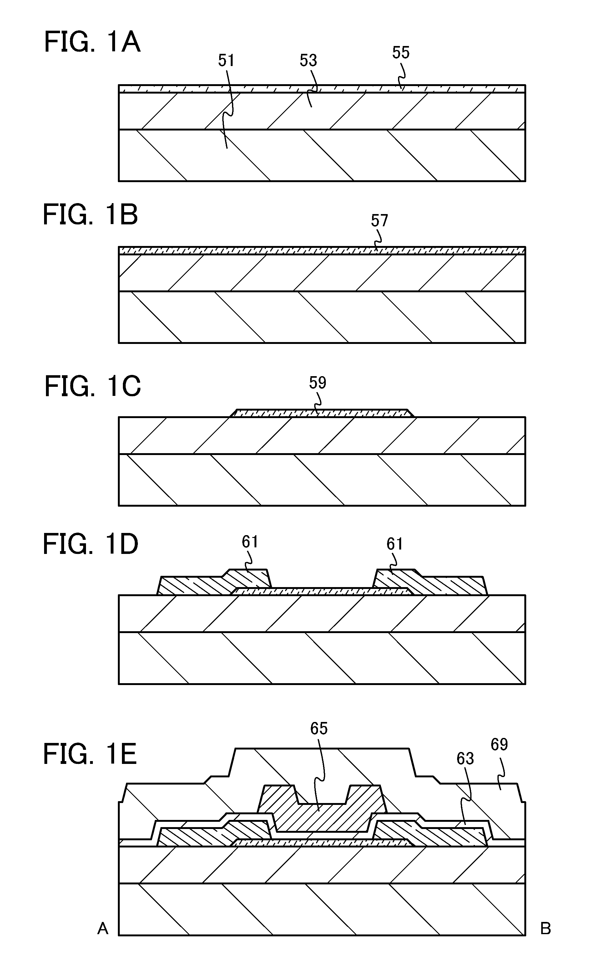
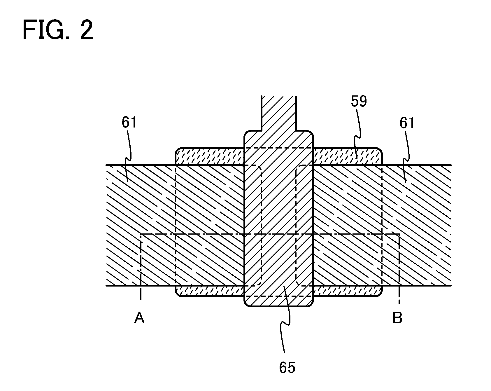
[0037]FIGS. 1A to 1E are cross-sectional views illustrating a manufacturing process of a transistor as one mode of a structure of a semiconductor device. The cross-sectional view taken along the dot-dash line A-B in FIG. 2 corresponds to FIG. 1E.

[0038]As illustrated in FIG. 1A, an oxide insulating film 53 is formed over a substrate 51, and an oxide semiconductor film 55 is formed over the oxide insulating film 53.

[0039]As the substrate 51, a glass substrate (also referred to as a “non-alkali glass substrate”), a quartz substrate, a ceramic substrate, a plastic substrate, or the like can be used as appropriate. Further, a flexible glass substrate or a flexible plastic substrate can be used as the substrate 51. As a plastic substrate, a substrate having low refractive index anisotropy is preferably used, and a polyether sulfone (PES) film, a polyimide film, a polyethylene naphthalate (PEN) film, a polyvinyl fluoride (PVF) film, a polyester film, a polycarbonate (PC) film, an acrylic r...

embodiment 2

[0088]In Embodiment 2, a manufacturing method of a transistor having a structure different from the transistor described in Embodiment 1 will be described with reference to FIGS. 3A to 3D, and FIG. 4. Embodiment 2 is different from Embodiment 1 in that a pair of electrodes is provided between an oxide insulating film and an oxide semiconductor film. Note that the cross-sectional view taken along the dot-dash line A-B in FIG. 4 corresponds to FIG. 3D.

[0089]As illustrated in FIG. 3A, the oxide insulating film 53 is formed over the substrate 51 as in Embodiment 1. A pair of electrodes 71 is formed over the oxide insulating film 53. An oxide semiconductor film 73 is formed over the pair of electrodes 71 and the oxide insulating film 53.

[0090]The pair of electrodes 71 can be formed as appropriate by using a material and by a formation method which are similar to those of the pair of electrodes 61 described in Embodiment 1.

[0091]The oxide semiconductor film 73 can be formed as appropriate...

embodiment 3

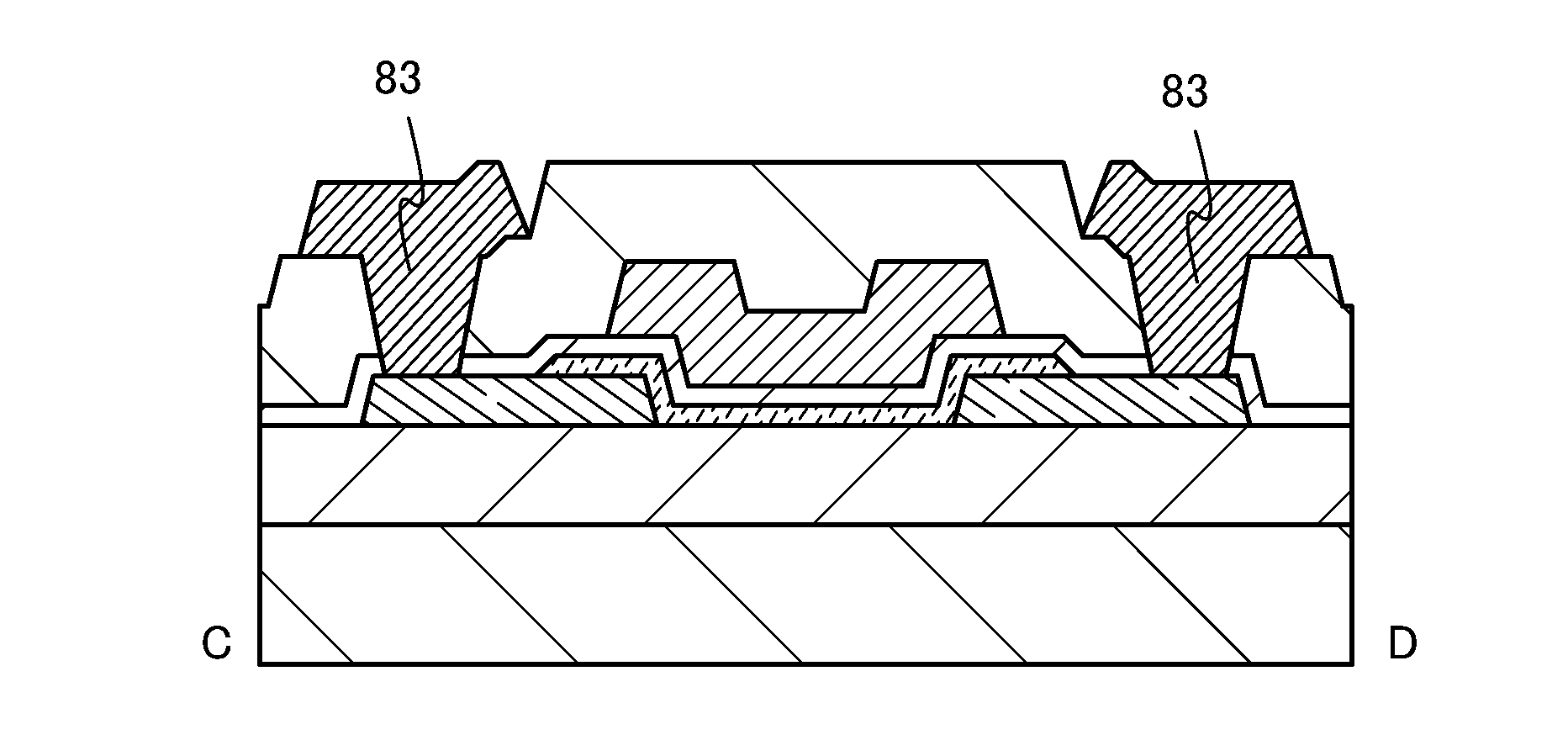
[0101]In Embodiment 3, a manufacturing method of a transistor where a contact resistance between an oxide semiconductor film and a pair of wirings can be decreased more than those of the transistors described in Embodiment 1 and Embodiment 2 will be described with reference to FIGS. 1A to 1E and FIGS. 5A to 5E.

[0102]As in Embodiment 1, in the steps illustrated in FIGS. 1A and 1B, the oxide semiconductor film 55 is formed over the oxide insulating film 53 and is heated to form the oxide semiconductor film 57 with the lowered hydrogen concentration and the reduced oxygen vacancies. Next, as illustrated in FIG. 5A, a buffer 84 having an n-type conductivity is formed over the oxide semiconductor film 57 with the lowered hydrogen concentration and the reduced oxygen vacancies.

[0103]For the buffer 84 having an n-type conductivity, a metal oxide selected from the group of indium oxide, indium tin oxide, indium zinc oxide, tin oxide, zinc oxide, and tin zinc oxide, or a material of the meta...


PUM


Abstract

A transistor with superior electric characteristics is manufactured. An oxide insulating film is formed over a substrate, an oxide semiconductor film is formed over the oxide insulating film, heat treatment is then conducted at a temperature at which hydrogen contained in the oxide semiconductor film is desorbed and part of oxygen contained in the oxide insulating film is desorbed, then the heated oxide semiconductor film is etched into a predetermined shape to form an island-shaped oxide semiconductor film, a pair of electrodes is formed over the island-shaped oxide semiconductor film, a gate insulating film is formed over the pair of electrodes and the island-shaped oxide semiconductor film, and a gate electrode is formed over the gate insulating film.

Description

BACKGROUND OF THE INVENTION[0001]1. Field of the Invention[0002]Embodiments of the present invention relate to a semiconductor device which includes a circuit including at least one semiconductor element such as a transistor, and a manufacturing method thereof. For example, embodiments of the present invention relate to an electronic device which includes, as a component, any of a power device mounted in a power circuit, a semiconductor integrated circuit including a memory, a thyristor, a converter, an image sensor, or the like, an electro-optical device typified by a liquid crystal display device, and a light-emitting display device including a light-emitting element.[0003]2. Description of the Related Art[0004]Transistors formed over a glass substrate or the like are manufactured using amorphous silicon, polycrystalline silicon, or the like, as typically seen in liquid crystal display devices. Although transistors including amorphous silicon have low field effect mobility, they c...

Claims


Application Information

Patent Timeline
Patent Type & Authority Patents(United States)
IPC IPC(8): H01L29/10H01L21/00H01L29/04
CPCH01L29/4908H01L29/66742H01L29/66969H01L29/7869H01L21/477H01L29/78603H01L21/324H01L29/66477H01L29/40114H01L21/02164H01L21/465H01L22/10
Inventor NODA, KOSEISASAKI, TOSHINARI
Owner SEMICON ENERGY LAB CO LTD
Why Eureka
Eureka Blog
Learn More