Temperature compensated bushing design

a bushing and temperature compensation technology, applied in the direction of manufacturing tools, mechanical equipment, insulation bodies, etc., can solve the problem of limiting the maximum cooling needs of the bushing, and achieve the effect of improving the prior art bushing

Active Publication Date: 2014-06-10
HITACHI ENERGY LTD
View PDF10 Cites 2 Cited by
  • Summary
  • Abstract
  • Description
  • Claims
  • Application Information

AI Technical Summary

Benefits of technology

[0014]It is an object of the present invention to provide a high voltage bushing that ensures that the contact pressure between the bottom contact and the conductor is nearly constant over the operational temperature range which improves prior art bushings.
[0017]An advantage of this invention is that the contact pressure between the bottom contact and the conductor is by design nearly constant over the operational temperature range independent of what the thermal expansion coefficient is for the conductor tube and the draw rod which improves prior art bushings by ensuring constant low losses in the contact or joint in the current path between different bottom contact and conductor in the bushing. The constant low losses ensure that the heat generation does not suddenly increase and this limits the maximal cooling needs of the bushing. The solution is simple to realize and do not require any special materials. Furthermore, the present invention minimizes the possibility for errors during assembly of the bushing.

Problems solved by technology

The constant low losses ensure that the heat generation does not suddenly increase and this limits the maximal cooling needs of the bushing.

Method used


Image

  • Temperature compensated bushing design
  • Temperature compensated bushing design
  • Temperature compensated bushing design

Examples


Embodiment Construction

[0037]Detailed descriptions of the preferred embodiment are provided herein. It is to be understood, however, that the present invention may be embodied in various forms.

[0038]In this description, the term “high voltage” (HV) will be used for voltages of 50 kV and higher. The present upper limit for commercial high voltage is 1100 kV, but it is foreseen that the invention can be used also for higher voltages, up to 1200 kV or even more. Generally, the present invention will find its applicability from about 200 kV and upwards.

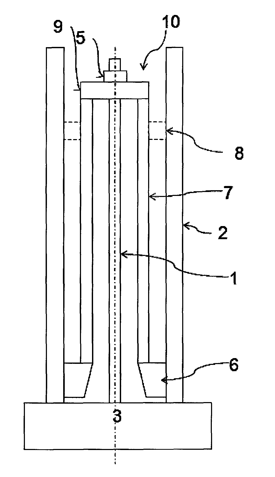
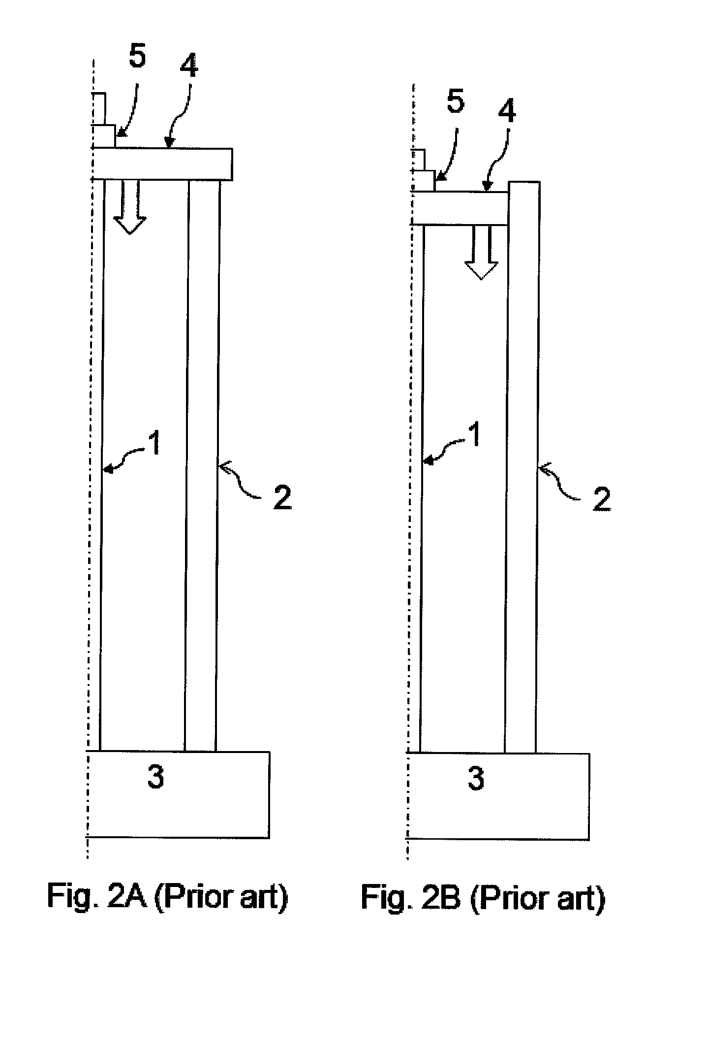
[0039]In FIG. 2A, one end of the draw rod 1 is fixed in the bottom contact 3, and in the other end of the draw rod 1 is arranged with a member 4 with a through hole for the draw rod and the member is in contact with the conductor, above the conductor. A clamping means 5 is attached to the draw rod, this forces the member 4 down onto the conductor 2, which ensures that the contact pressure between the conductor 2 and the bottom contact 3 is sufficient.

[0040]In t...


PUM

PropertyMeasurementUnit
voltagesaaaaaaaaaa
currentaaaaaaaaaa
lengthaaaaaaaaaa

Abstract

A bushing including a bottom contact, and a tubular conductor, having a lower part having an end in electrical and mechanical contact with the bottom contact, and a draw rod arrangement, inside the conductor, arranged to exert sufficient contact pressure between the bottom contact and the conductor, and the draw rod arrangement includes a member in mechanical contact with the conductor and draw rod having a second end, fixedly connected to the bottom contact, and a first end in connection to the member and clamping means, the clamping means is adapted to apply a force, urging the member in the direction of the bottom contact to generate sufficient contact pressure between the bottom contact and the conductor. The member of the draw rod arrangement is arranged to apply the force to the lower part of the conductor.

Description

FIELD OF THE INVENTION[0001]The present invention relates to the field of high voltage power systems, and in particular to high voltage bushings used in high voltage devices, such as transformers or reactors, forming parts of such systems.BACKGROUND OF THE INVENTION[0002]It is known that high voltage equipment and devices, e.g. high voltage transformers, reactors, switchgear etc., are usually equipped with bushings that are adapted for carrying current at high potential through a grounded barrier, e.g. a wall or an enclosure of the electric device such as a transformer tank.[0003]Conventional high voltage bushings comprise a hollow tube electrical conductor. The electrical conductor connects one side of the bushing, where a high voltage electric device is connected, with the other side of the bushing where another electric device is connected. For example, when the first electric device is a transformer, the bushing is fitted on the transformer enclosure and the conductor of the bus...

Claims


Application Information

Patent Timeline
Patent Type & Authority Patents(United States)
IPC IPC(8): H02G3/22H01B17/26H01B17/00
CPCH02G3/22H01B17/26H01B17/28H01B17/005Y10T16/05Y10T16/063H01F27/04
Inventor ERIKSSON, THOMASSJOBERG, PETER
Owner HITACHI ENERGY LTD
Why Eureka
Try Eureka