Jet assisted tubeless tire seating device

a tubeless tire and seat technology, applied in the field of tools, can solve the problems of large air tank, dangerously high pressure to achieve the effect of seating large tires, and the inability to seat tires

Active Publication Date: 2014-06-17
GAITHER TOOL COMPANY
View PDF14 Cites 8 Cited by
  • Summary
  • Abstract
  • Description
  • Claims
  • Application Information

AI Technical Summary

Problems solved by technology

But in some cases, especially with larger tires, it is just not possible to seat the tire by injecting air through the valve stem of the rim.
This may lead to a large unwieldy air tank and / or dangerously high pressures to accomplish this for large tires.

Method used


Image

  • Jet assisted tubeless tire seating device
  • Jet assisted tubeless tire seating device
  • Jet assisted tubeless tire seating device

Examples


Embodiment Construction

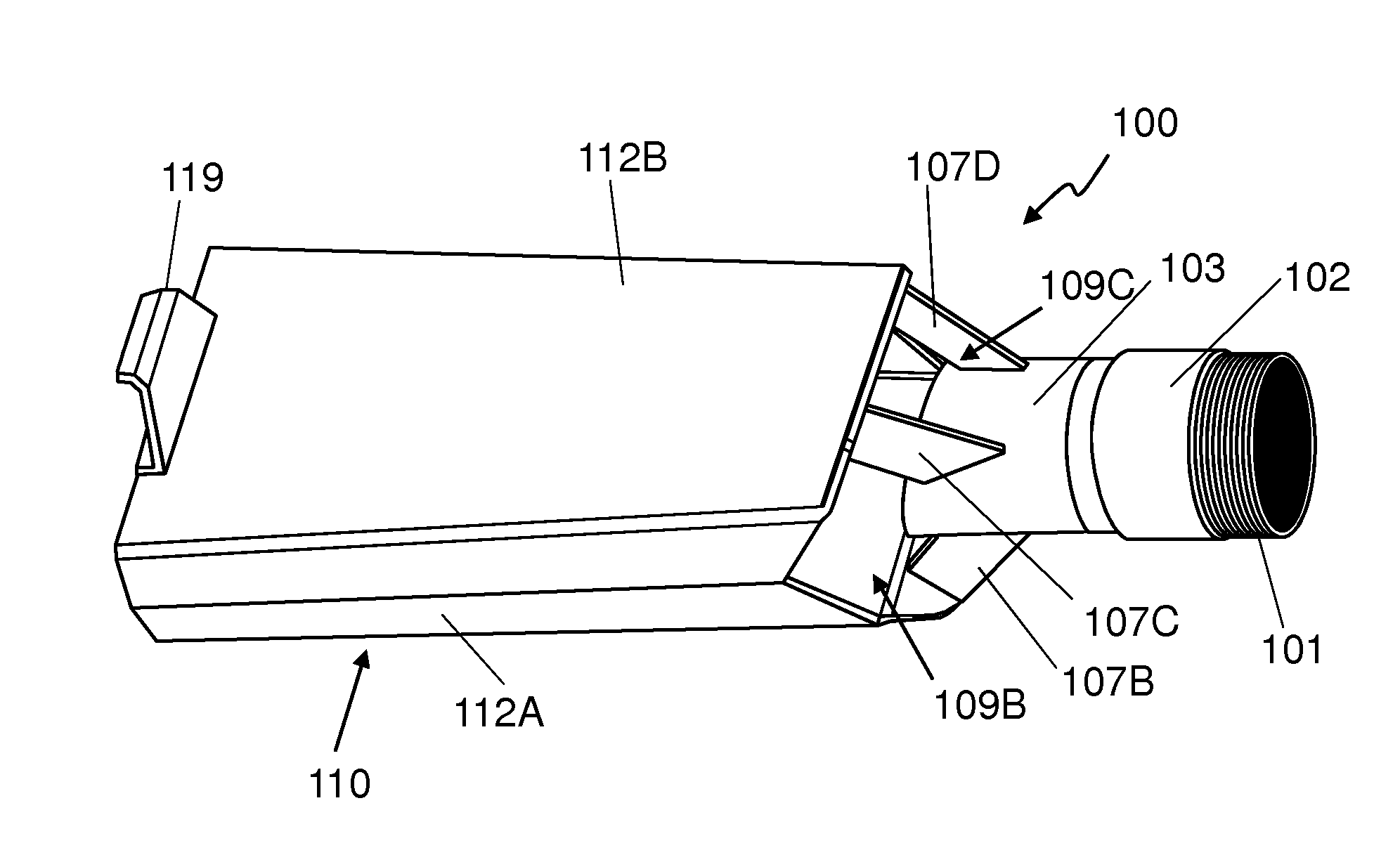
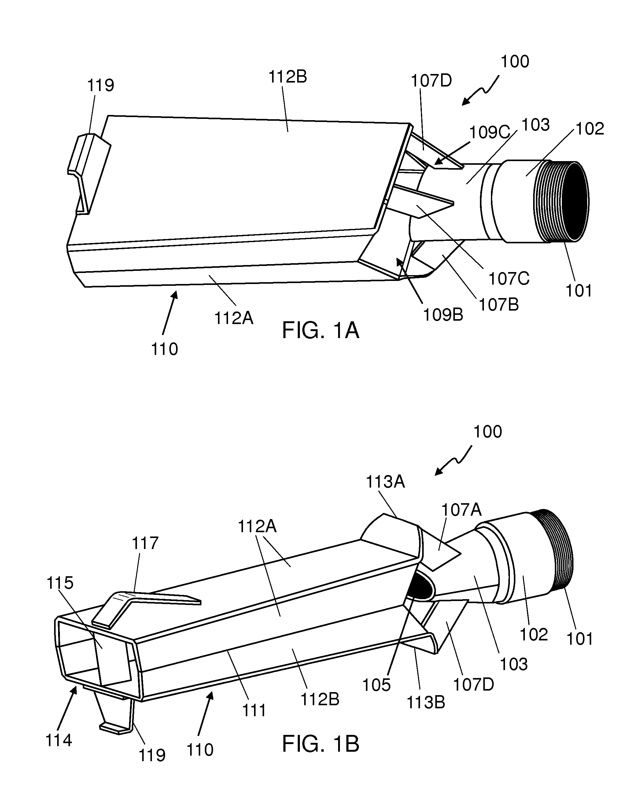
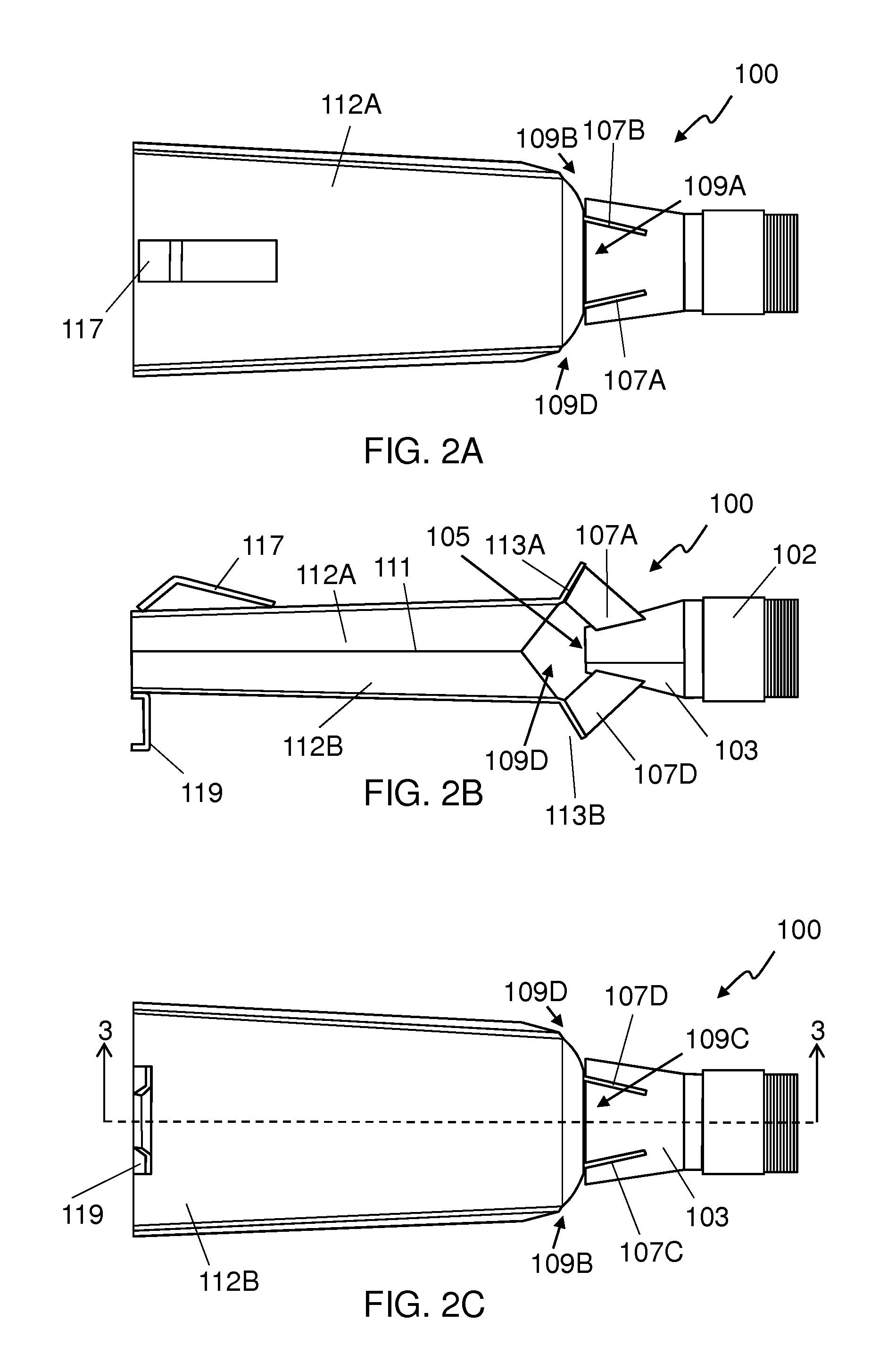
[0018]The present inventor recognized a problem with conventional design. Namely, the conventional designs feature a tank size that is either too large (for sufficient air volume) or too heavily reinforced (for sufficient pressure) in order to attain a burst of air sufficient to mount a tubeless tire on a wheel rim. The inventor recognized the benefits of being able to use a smaller more easily portable tank. The present invention alters the design of a conventional nozzle to provide a higher speed burst and greater volume of air into the tire for a given tank size. In this way nozzles according to the various embodiments disclosed herein can be used with smaller, more easily portable, sized tanks.

[0019]In the following detailed description, numerous specific details are set forth by way of examples in order to provide a thorough understanding of the relevant teachings. However, it should be apparent to those skilled in the art that the present teachings may be practiced without suc...


PUM

PropertyMeasurementUnit
angleaaaaaaaaaa
angleaaaaaaaaaa
angleaaaaaaaaaa

Abstract

A nozzle for seating a tubeless tire on a rim using pressurized gas includes an outlet, a jet configured to accept pressurized gas and emit a stream of gas through an orifice into a chamber. As the stream of gas enters the chamber, the Venturi effect causes air to enter the chamber through air intake ports and the stream of gas and air from the air intake ports is blown out of the outlet of the nozzle. A system for seating a tubeless tire on a rim includes the nozzle, a tank and a valve configured to control the flow of pressurized gas from the tank to the nozzle. The tire may be seated on the rim by positioning the system so that the air from the nozzle blows into the tire between the bead of the tire and the rim if the valve is opened.

Description

CROSS-REFERENCE TO RELATED APPLICATIONS[0001]This application claims the benefit of and priority to U.S. Provisional Application 61 / 342,316 filed Apr. 14, 2010 which is incorporated herein by reference in its entirety.BACKGROUND[0002]1. Technical Field[0003]The present subject matter relates to tools. More specifically, the present subject matter relates to a tool for seating a tubeless tire on a rim.[0004]2. Description of Related Art[0005]Many tires for automobiles, trucks and other equipment are designed to be mounted on wheels or rims without using a tube. The tire may be impervious to air with a bead around the inner edges of the tire designed to press against a lip of the rim to create an air-tight seal so that the combination of the tire and rim may be able to hold pressurized air or other gases. The rim may include a valve stem that may be used to inflate the tire.[0006]After a tire is first mounted on a rim, the bead of the tire may not press tightly against the lip of the ...

Claims


Application Information

Patent Timeline
Patent Type & Authority Patents(United States)
IPC IPC(8): B60C25/14B60C25/00B60C25/132B60S5/04B60B31/00
CPCB60B31/005B60C25/132B60S5/04B60C25/147B60C25/145Y10T29/49494
Inventor KUNAU, DANIEL
Owner GAITHER TOOL COMPANY
Why Eureka
Try Eureka