
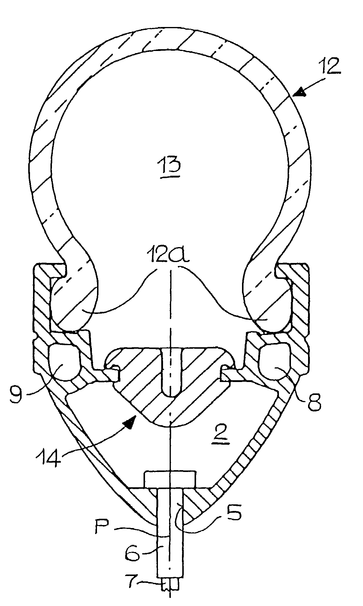
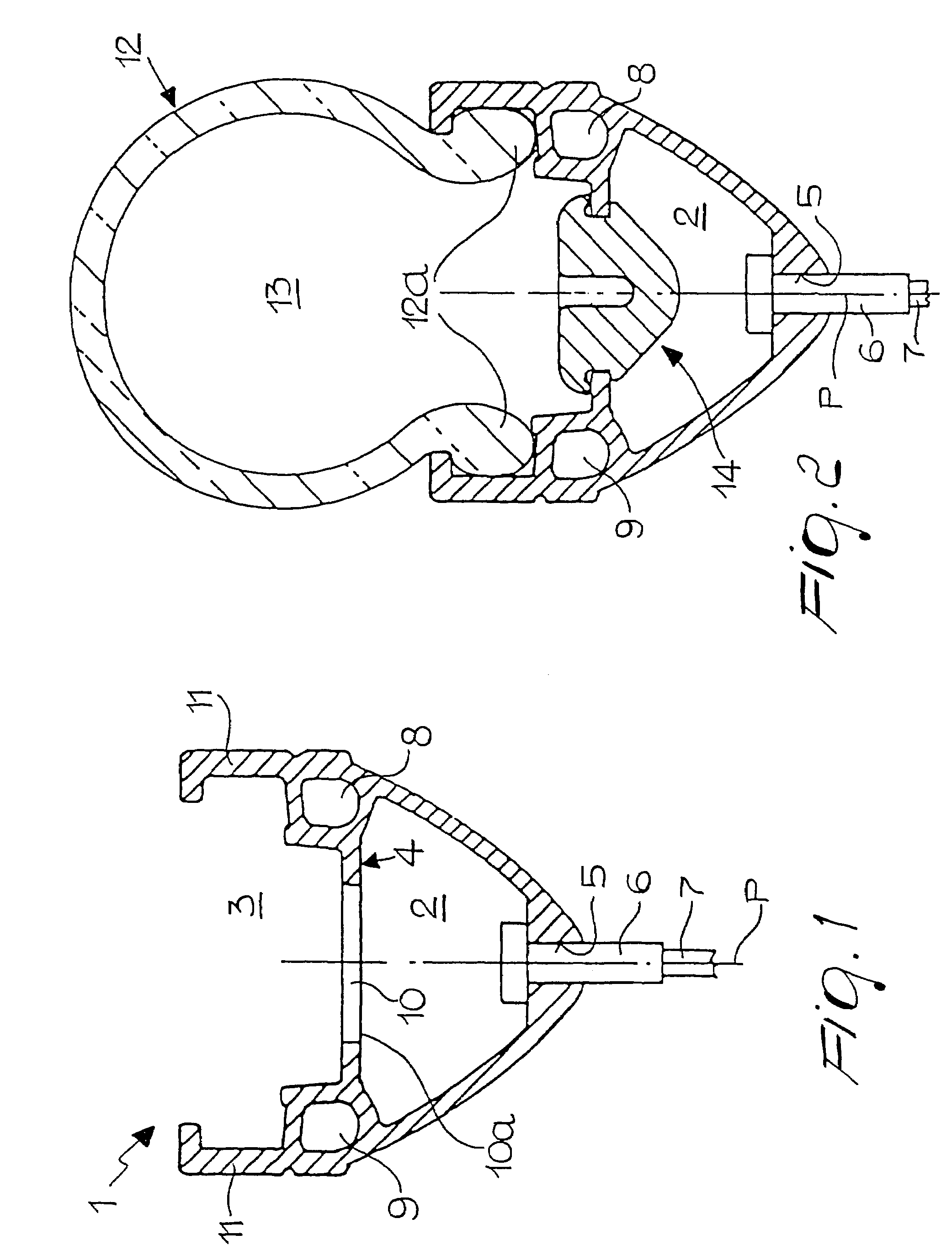
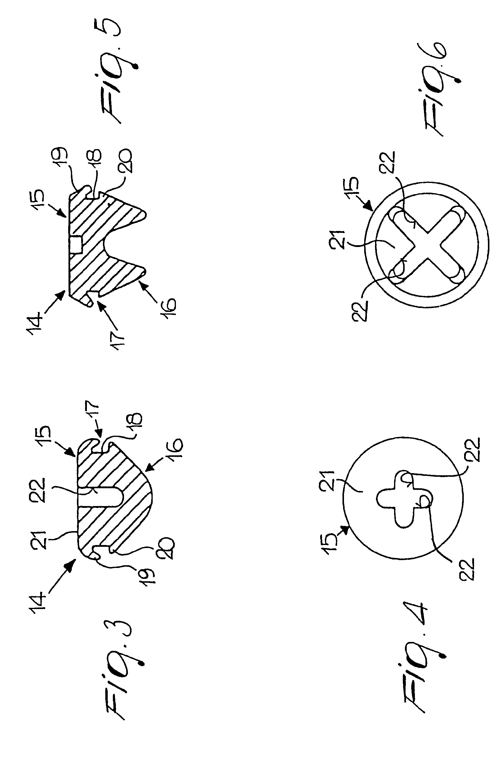
Rim for mounting tubeless tires, particularly for bicycles, motorcycles and mopeds

a tubeless tire and rim technology, which is applied to rims, wheels, spoked wheels, etc., can solve the problem that rims cannot be used as means for supporting tubeless tires

Inactive Publication Date: 2008-05-20
ALPINA RAGGI
View PDF21 Cites 8 Cited by
  • Summary
  • Abstract
  • Description
  • Claims
  • Application Information

AI Technical Summary

Benefits of technology

[0006]Within this aim, an object of the present invention is to provide a rim that can have usefulness and economical industrial application.
[0007]Still another object of the present invention is to provide a structure that is simple, relatively easy to provide in practice, safe in use and effective in operation.

Problems solved by technology

These rims have a severe drawback, which is due to the fact that they only allow mounting of conventional tires and therefore necessarily entail interposing an inner tube between the receptacle and the tire; accordingly, such rims cannot be used as means for supporting tubeless-type tires.

Method used


Image

  • Rim for mounting tubeless tires, particularly for bicycles, motorcycles and mopeds
  • Rim for mounting tubeless tires, particularly for bicycles, motorcycles and mopeds
  • Rim for mounting tubeless tires, particularly for bicycles, motorcycles and mopeds

Examples


third embodiment

[0029]A third embodiment is shown in the accompanying drawings 7 to 10.

[0030]In this third embodiment, the closure elements consist of sealing plugs 23 having a frustum-like shape that forms a head 24 and a shank 25 which can expand and are provided with respective coaxially opposite cylindrical cavities 26 and 27. The head 24 comprises an annular groove 28, which is delimited in an upward region by an expandable lip 29 and in a downward region by a tooth 30. The expandable lip 29 and the tooth 30 form opposite abutments 29a, 30a which, by acting against the outer and inner edges of the slot 10, prevent the axial extraction of the sealing plug 23.

[0031]Complementary sealing plugs 31 are detachably associated with the sealing plug 23 and have a head 32 and a shank 33 on which expansion elements 38, constituted by frustum-shaped annular protrusions 39, are provided. The complementary sealing plug 31 is inserted with its shank 33 in the cylindrical cavity 26, which by way of the transv...

fourth embodiment

[0033]In a fourth embodiment, FIGS. 11 and 12, the expansion elements 38 are constituted by a threaded expandable insert 39, which is accommodated substantially at the bottom of the cavity 26. In this case, the complementary plug 31 is screwed into the insert 39 through the cavity 26, and said insert 39, by expanding against the walls of said cavity 26, causes the head 24 to expand.

fifth embodiment

[0034]Conveniently, the sealing plug 23 is provided which has a head 24 and a shank 25 having a cylindrical shape. The sealing plug 23 is designed to removably enter the slot 10, which protrudes into the outer annular seat 2 by means of an undercut 40. The insertion and sealing of the sealing plug in the slot 10 are achieved by way of sealing means, which in this case consist of corresponding helical threads 41, 42 provided respectively on the facing surfaces of the shank 25 and of the undercut 40. Furthermore, in order to increase the seal and improve the hermetic separation between the outer annular seat 2 and the inner one 3, a ring 43 is interposed between the head and the passage hole.


PUM


Abstract

A rim for mounting tubeless tires, particularly for bicycles, motorcycles and mopeds, constituted by a profiled element which is curved in a circular fashion and is symmetrical with respect to a centerline plane (P), said profiled element forming an outer annular seat (2) and an inner annular seat which are divided by an annular partition provided with slots arranged opposite the nipples (6) associated with the spokes of said rim, a tire of the tubeless type being associated with said outer annular seat so as to form a pressure chamber. The rim comprises closure elements that engage said slots in order to hermetically separate said outer annular seat from said inner annular seat.

Description

BACKGROUND OF THE INVENTION[0001]The present invention relates to a rim for mounting tubeless tires, particularly for bicycles, motorcycles and mopeds.[0002]Rims for accommodating tires of the conventional type are already known and are constituted by a profiled element which is curved in a circular fashion, is symmetrical with respect to a centerline plane, and forms an outer annular seat and an inner annular seat; the outer and inner annular seats are divided by an annular partition provided with slots. The outer annular seat is provided, on the side directed toward the center of the rim, with coupling holes through which slots guide nipples for connecting the spokes to the rim. The inner annular seat defines lateral shoulders, which form a receptacle for retaining the beads of the tire.[0003]These rims have a severe drawback, which is due to the fact that they only allow mounting of conventional tires and therefore necessarily entail interposing an inner tube between the receptac...

Claims


Application Information

Patent Timeline
Patent Type & Authority Patents(United States)
IPC IPC(8): B60B21/12B60B1/04B60B21/00
CPCB60B1/041B60B1/044B60B21/00B60B21/025B60B21/04B60B21/12
Inventor FIORAVANTI, MORENO
Owner ALPINA RAGGI
Learn More